


Architecture diagrams serve as the blueprint for software systems. They translate abstract logic into visual structures that teams can understand, discuss, and build upon. While the C4 model provides a structured approach to documenting software architecture, specific challenges arise when representing security-critical processes like authentication. A generic component diagram often glosses over the nuances of identity verification, token exchange, and session management.
This guide details how to represent authentication flows within the C4 Component View. We will explore the semantic meaning of diagram elements, how to delineate security boundaries, and the best practices for mapping complex identity logic without relying on proprietary tools. The goal is clarity, precision, and maintainability in your documentation.
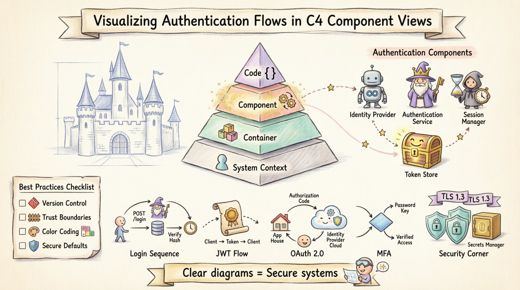
🧩 Understanding the C4 Model Context
The C4 model organizes architecture documentation into four levels of abstraction:
- System Context: Shows the system as a single box and its relationships with people and other systems.
- Container: Breaks the system into high-level software containers (e.g., web apps, mobile apps, microservices, databases).
- Component: Decomposes containers into smaller, cohesive units of functionality.
- Code: Details the internal structure of classes and interfaces within components.
Authentication logic is critical enough that it often requires attention at the Container and Component levels. The Container View might show where authentication endpoints exist, but the Component View reveals the internal mechanics of how credentials are processed and validated.
🔍 Why the Component View for Authentication?
The Component View is the most granular layer suitable for high-level architecture documentation. It is ideal for authentication for several reasons:
- Logic Visibility: It exposes the specific services handling login requests, token generation, and session validation.
- Interaction Clarity: It clarifies how the front-end interacts with back-end security services.
- Boundary Definition: It helps define what is inside the trusted system versus what is external.
When documenting authentication, you are not just drawing boxes. You are documenting the flow of sensitive data. A well-drawn component diagram reduces ambiguity about where secrets are stored and how they travel.
📦 Defining Authentication Components
To visualize authentication effectively, you must first identify the distinct components that participate in the process. These components should be named to reflect their function rather than their implementation.
Core Identity Components
- Identity Provider: An external system responsible for issuing credentials or tokens. This could be a third-party service or an internal service.
- Authentication Service: The internal component responsible for verifying credentials (e.g., checking passwords against a hash).
- Session Manager: A component responsible for creating, maintaining, and destroying user sessions.
- Token Store: A repository for storing issued tokens, often used for refresh tokens or blacklisting.
External Dependencies
Authentication rarely happens in isolation. Your diagram must show the relationship between your components and external identity sources.
| Component Type | Diagram Representation | Example Label |
|---|---|---|
| External System | Rectangle with “External” icon or border style | Identity Provider |
| Database | Cylinder shape | User Credential Store |
| API Endpoint | Box with arrow indicators | Auth Endpoint |
🔄 Visualizing Specific Authentication Flows
A static diagram shows structure, but a flow adds dynamic context. For authentication, you need to show how data moves between components. Use directed arrows to represent requests and responses.
1. The Login Sequence
The most common flow involves a user providing credentials. In a component diagram, this looks like a sequence of interactions.
- Step 1: The Frontend Component sends a request to the Authentication Service.
- Step 2: The Authentication Service queries the User Store.
- Step 3: The User Store returns the hashed credential.
- Step 4: The Authentication Service validates the hash.
- Step 5: The Authentication Service signals the Session Manager to create a session.
On the diagram, label these arrows with the protocol or action, such as POST /login or Verify Hash.
2. Token-Based Authentication (JWT)
Modern systems often rely on JSON Web Tokens (JWT). This requires showing the issuance and validation flow.
- Issuance: The Authentication Service generates the token after successful login.
- Transmission: The token is sent to the client (Frontend).
- Validation: Subsequent requests include the token.
- Verification: The API Gateway or a specific Auth Component validates the signature.
When drawing this, distinguish between the initial request and the subsequent protected requests. Use dashed lines for the token transmission to imply it is a credential passed by the client rather than a direct system-to-system call.
3. OAuth 2.0 Flows
When integrating with external providers, the flow is more complex. You must show the redirection of the user agent.
- Redirect: The Application sends the user to the Identity Provider.
- Callback: The Identity Provider sends the user back with an authorization code.
- Token Exchange: The Application exchanges the code for an access token.
In the diagram, represent the Identity Provider as an external component. Draw a loop from the Application to the Provider and back. Label the callback arrow clearly with Authorization Code.
4. Multi-Factor Authentication (MFA)
MFA introduces a conditional path in your diagram. You should represent this using a decision node or a separate branch.
- Primary Check: Password verification.
- Secondary Check: If MFA is enabled, route to the MFA Component.
- Verification: The MFA Component validates the code.
- Completion: Only then does the Session Manager activate.
Visualizing this prevents developers from assuming a single step is sufficient for security. It highlights the additional component required for the second factor.
🔒 Security Considerations in Diagrams
A diagram is not just a map of data; it is a map of trust. You must explicitly mark where security boundaries exist.
Encryption and Transport
Always indicate when data is encrypted in transit. You can use a lock icon next to the connection line or label the arrow with HTTPS or TLS 1.3.
- In Transit: All communication between components and external systems should be marked as encrypted.
- At Rest: Indicate if the User Store encrypts data at rest.
Storage of Secrets
One of the most critical aspects of authentication diagrams is showing where secrets are stored.
- Secrets Manager: If you use a dedicated service for API keys or client secrets, include it as a component.
- Environment Variables: If secrets are injected at runtime, note this in the component description.
- Never in Code: Ensure the diagram does not imply secrets are hardcoded. Use a generic “Configuration Source” component if necessary.
🛑 Common Pitfalls to Avoid
When documenting authentication flows, it is easy to introduce confusion. Here are common mistakes and how to correct them.
| Pitfall | Correction |
|---|---|
| Generic Labels | Use specific terms like “Validate Token” instead of “Process”. |
| Missing External Dependencies | Always show where tokens come from, even if it is an external provider. |
| Ignoring Refresh Tokens | Include the flow for token renewal to show lifecycle management. |
| Overcomplicating the View | Keep the Component View focused on logic. Move code-level details to the Code View. |
📝 Best Practices for Documentation
Consistency is key for maintainable documentation. Follow these guidelines to ensure your diagrams remain useful over time.
- Standardize Notation: Decide on a specific style for arrows, boxes, and icons. Document this style guide.
- Version Control: Treat diagrams as code. Store them in version control to track changes in logic.
- Review Cycles: Include diagram updates in your code review process. If the auth logic changes, the diagram must change.
- Focus on Trust Boundaries: Clearly mark where the system trust ends and the external environment begins.
- Use Color Sparingly: If using colors, limit them to indicating security states (e.g., red for sensitive data, green for public). Avoid using color as the primary means of distinction.
🧠 Detailed Flow Example: User Registration
To illustrate the depth required, consider the registration flow. This involves creating a new identity.
- User Input: The Registration Component receives email and password.
- Validation: The component checks format (email regex, password strength).
- Uniqueness Check: The component queries the User Store to ensure the email does not exist.
- Hashing: The component generates a salted hash of the password.
- Storage: The component writes the new record to the User Store.
- Verification: The component sends a verification token via the Email Service.
On the diagram, ensure the Email Service is visible as an external dependency. This clarifies that the user cannot access the account until the external step is completed.
🧠 Detailed Flow Example: Token Refresh
Access tokens expire. The refresh mechanism is often overlooked in diagrams but is vital for user experience and security.
- Request: The client sends a refresh token to the Auth Service.
- Validation: The Auth Service checks the token validity and not-before time.
- Revocation: If the token has been used or revoked, the request is rejected.
- Issuance: New access and refresh tokens are generated.
- Rotation: The old refresh token is invalidated to prevent replay attacks.
Label the “Rotation” step clearly. This indicates a security best practice where tokens are not just reused but rotated.
🧠 Detailed Flow Example: Session Invalidation
Logout is not just closing a window. It involves server-side state cleanup.
- Request: The client sends a logout request.
- Token Blacklist: The Auth Service adds the token to a blacklist store.
- Session Delete: The Session Manager removes the session data.
- Response: The client is notified that the session is terminated.
This flow ensures that a stolen token cannot be used after the user logs out. It is a critical component of security architecture.
📊 Comparing Auth Strategies in Diagrams
Different strategies require different diagrammatic representations. Understanding these differences helps you choose the right view.
| Strategy | Diagram Focus | Key Component |
|---|---|---|
| Session-Based | Server-side storage | Session Store |
| Token-Based | Cryptographic signing | Token Generator |
| Third-Party | Redirect and Callback | Identity Provider |
🚀 Conclusion on Visualization
Visualizing authentication flows is about more than drawing boxes. It is about communicating security posture and data integrity. By adhering to the C4 model and focusing on the Component View, you create a document that serves both developers and security auditors.
Remember to keep the diagram updated. As authentication requirements evolve, your visual representation must evolve with them. Clear diagrams reduce cognitive load for new team members and provide a reference point during incident response.
When you draw a connection line, ask yourself: “Does this line represent a trusted communication channel?” When you draw a box, ask: “Does this component handle sensitive data?” These questions will guide you toward diagrams that are not just pretty, but secure and accurate.
By following these guidelines, you ensure that your architecture documentation remains a living asset. It becomes a tool for understanding, not just a record of the past. This approach fosters a culture of security awareness within the development team.
- C4 Diagram Tool by Visual Paradigm – Visualize Software Architecture with Ease: This resource highlights a tool that enables software architects to create clear, scalable, and maintainable system diagrams using the C4 modeling technique.
- Ultimate Guide to C4 Model Visualization Using Visual Paradigm’s AI Tools: This guide explains how to leverage artificial intelligence to automate and enhance the visualization of the C4 model for smarter architecture design.
- Leveraging Visual Paradigm’s AI C4 Studio for Streamlined Architecture Documentation: An exploration of the AI-enhanced C4 Studio, which allows teams to create clean, scalable, and highly maintainable software architecture documentation.
- Beginner’s Guide to C4 Model Diagrams: A step-by-step tutorial designed to help beginners create C4 model diagrams across all four levels of abstraction: Context, Containers, Components, and Code.
- The Ultimate Guide to C4-PlantUML Studio: Revolutionizing Software Architecture Design: This article discusses the integration of AI-driven automation with PlantUML’s flexibility to streamline the software architecture design process.
- A Comprehensive Guide to Visual Paradigm’s AI-Powered C4 PlantUML Studio: A detailed guide explaining how this specialized studio transforms natural language into accurate, layered C4 diagrams.
- C4-PlantUML Studio: AI-Powered C4 Diagram Generator: This feature overview describes an AI tool that automatically generates C4 software architecture diagrams directly from simple text descriptions.
- Comprehensive Tutorial: Generating and Modifying C4 Component Diagrams with AI Chatbot: A hands-on tutorial demonstrating how to use an AI-powered chatbot to generate and refine C4 component diagrams through a real-world case study.
- Visual Paradigm Full C4 Model Support Release: An official announcement regarding the inclusion of comprehensive C4 model support for managing architecture diagrams at multiple abstraction levels within the platform.
- C4 Model AI Generator: Automating Diagrams for DevOps and Cloud Teams: This article discusses how conversational AI prompts automate the full C4 modeling lifecycle, ensuring consistency and speed for technical teams.