


In the intricate landscape of software development, communication often becomes the primary bottleneck. Teams frequently find themselves navigating complex systems where technical debt accumulates not just in code, but in documentation. One of the most persistent challenges is the lack of a shared language when describing system structures. Without a standard vocabulary, diagrams become personal interpretations rather than organizational assets. This guide explores how to establish a consistent lexicon for software architecture diagrams, specifically leveraging the principles of the C4 Model to ensure clarity and longevity.
When architects and developers speak, they should refer to the same concepts with the same definitions. Ambiguity leads to misalignment. If one person defines a “container” as a microservice while another views it as a database, the resulting architecture documentation becomes noise. By standardizing this vocabulary, teams can reduce cognitive load and accelerate decision-making processes. The goal is not to restrict creativity but to provide a robust framework for expression.
📉 The Cost of Ambiguity in Architecture Documentation
Consider the scenario where a new engineer joins a project. They are handed a set of diagrams to understand the system. If these diagrams use inconsistent terminology, the onboarding process slows down significantly. The new hire must spend time deciphering what a specific box represents rather than learning how the system functions. This friction impacts velocity and morale.
Beyond onboarding, ambiguity creates risks in maintenance. When a bug appears in production, the team needs to trace the flow of data. If the diagram labels a service as “Payment Handler” in one view and “Billing Module” in another, the investigation becomes a scavenger hunt. Standardization acts as a contract between the team members. It ensures that the documentation remains a source of truth rather than a source of confusion.
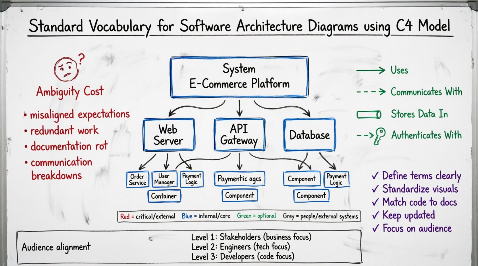
Key issues arising from poor vocabulary include:
- Misaligned Expectations: Stakeholders may expect a different level of detail than what is provided.
- Redundant Work: Developers may build features thinking they are part of an existing module, only to duplicate functionality.
- Documentation Rot: If the effort to update diagrams is too high due to unclear standards, the docs become outdated quickly.
- Communication Breakdowns: Meetings become debates about definitions rather than technical solutions.
🧩 The C4 Model as a Foundational Framework
To address these challenges, many organizations adopt the C4 Model. This model provides a hierarchical approach to diagramming, allowing teams to zoom in and out of their systems without losing context. It is not a rigid set of rules but a set of guidelines for structuring information. The model distinguishes between four levels of abstraction: Context, Container, Component, and Code.
Adopting this model helps in establishing a vocabulary because it forces the team to define what constitutes a “System” versus a “Container.” It moves the conversation away from vague terms like “module” or “layer” and towards specific architectural elements. This structure supports the creation of diagrams that are both high-level for executives and detailed enough for engineers.
The benefits of this hierarchical approach are:
- Consistency: Every diagram follows the same structural logic.
- Scalability: You can add new diagrams as the system grows without changing the core definitions.
- Clarity: Each level answers a specific question for a specific audience.
🔍 Defining the Core Vocabulary: Systems and Containers
At the heart of the C4 Model are the terms “System” and “Container.” These are often confused, yet they serve distinct purposes in the architectural vocabulary.
🏢 What is a System?
In the context of the Context Diagram (Level 1), a “System” refers to the entire software solution being described. It is the top-level boundary. For example, if you are building an e-commerce platform, the entire platform is the “System.” This includes all the services, databases, and interfaces required to make the business function.
When defining a System, the vocabulary should focus on its purpose and its users. The System is a black box to the external world. It accepts inputs from people or other systems and produces outputs. It does not care about the internal implementation details at this stage.
📦 What is a Container?
Moving to Level 2, the Container diagram, we break the System down. A “Container” is a distinct unit of deployment. It is something that runs code. Examples include web applications, mobile apps, microservices, or databases.
A container is a physical or logical runtime environment. It is important to distinguish this from a “Component.” A container is where code executes. A component is a piece of logic inside that code. For instance, a Web Application is a container. The authentication module inside that web application is a component.
Table 1 below summarizes the distinction:
| Term | Definition | Example | Diagram Level |
|---|---|---|---|
| System | The entire software solution | E-Commerce Platform | Level 1 (Context) |
| Container | A distinct unit of deployment | Web Server, API Gateway, Database | Level 2 (Container) |
| Component | A logical grouping of functionality | Order Service, User Manager | Level 3 (Component) |
🧱 Understanding Components and Code
As we drill down further, the vocabulary becomes more specific to the engineering team. The Component diagram (Level 3) describes the internal structure of a container. Here, we use the term “Component” to denote a logical grouping of related functionality.
Components are not physical artifacts. They do not have a direct deployment footprint. You cannot deploy a component on its own. You deploy the container that holds the components. This distinction is vital for avoiding confusion in infrastructure planning. When discussing components, the focus is on separation of concerns and cohesion.
For example, within a “Order Processing” container, you might have components for “Inventory Check,” “Tax Calculation,” and “Payment Processing.” These components work together to fulfill the container’s purpose. By naming them consistently, developers can locate the code responsible for specific business rules without guessing.
📝 Naming Conventions for Components
To maintain a standard vocabulary, naming conventions are essential. A component name should describe its responsibility. Avoid generic names like “Module A” or “Logic 1.” Instead, use descriptive nouns.
- Bad: DataHandler
- Good: CustomerDataProcessor
- Bad: Service1
- Good: NotificationService
This practice helps when searching through codebases or documentation. It also aids in automated documentation generation, as many tools rely on class names to populate diagrams.
🎨 Visual Grammar and Relationship Semantics
A vocabulary is not just about words; it is also about symbols. The lines connecting the boxes in a diagram carry meaning. Standardizing these relationships ensures that the visual language matches the spoken language.
🔗 Types of Relationships
Different types of lines indicate different interactions. A standard vocabulary for relationships includes:
- Uses: Indicates a dependency. One system calls another, but does not necessarily own the other.
- Communicates With: Indicates data flow. Information moves between two systems.
- Stores Data In: Indicates a persistent relationship. A system writes to a database.
- Authenticates With: Indicates a security relationship.
When defining these relationships in your vocabulary, ensure that the direction of the arrow is consistent. Does the arrow point to the caller or the callee? A common convention is that the arrow points to the thing being called. This should be documented in your style guide so all team members follow the same rule.
🎨 Color Coding Strategy
While black and white is standard for printing, color can enhance readability in digital formats. However, color should not be used arbitrarily. Assign meaning to colors and stick to it.
- Red: Critical systems or external dependencies.
- Blue: Internal containers or core services.
- Green: Optional or background services.
- Grey: People or external systems.
Do not overuse color. If every box is a different color, the diagram becomes a distraction. Use color to highlight specific states or categories, such as “Deprecated,” “Beta,” or “Production Only.” This adds a semantic layer to the visual representation.
🔄 Levels of Abstraction and Audience Alignment
One of the most common mistakes in architecture documentation is trying to fit all information into a single diagram. A standard vocabulary helps define the boundaries of each diagram type. Each level serves a specific audience with specific needs.
👥 Level 1: The Context Diagram
Audience: Stakeholders, Product Managers, New Hires.
Focus: What does the system do? Who uses it? Where does it fit in the ecosystem?
Vocabulary: Focus on business capabilities and external systems. Avoid technical jargon like “API Gateway” unless it is critical to the business flow.
🏗️ Level 2: The Container Diagram
Audience: Senior Engineers, DevOps, Architects.
Focus: How is the system built? What technologies are used? How are data flows managed?
Vocabulary: Focus on deployment units. Use terms like “Service,” “Database,” “Application,” and “File Store.” Discuss protocols like HTTP, SQL, or GraphQL.
🧩 Level 3: The Component Diagram
Audience: Development Team, Code Owners.
Focus: What is inside the container? How is the code structured?
Vocabulary: Focus on classes, modules, and functions. Discuss internal logic and data structures. This is where the implementation details live.
🛠️ Implementation Steps for a Standard Vocabulary
Establishing this vocabulary is not a one-time event. It requires a deliberate process. Below is a step-by-step approach to implementing these standards within a team.
- Assess Current State: Review existing diagrams. Identify inconsistencies in naming and symbolism. Note where confusion arises.
- Define the Style Guide: Create a document that outlines the definitions of System, Container, and Component. Define the relationship lines and color schemes. Make this accessible to everyone.
- Train the Team: Conduct workshops. Walk through examples. Show what a good diagram looks like versus a bad one.
- Integrate into Workflow: Make diagram updates part of the pull request process. If a feature changes the architecture, the diagram must be updated.
- Regular Audits: Schedule quarterly reviews. Check if the vocabulary is being followed. Identify new patterns that need definition.
⚠️ Common Pitfalls to Avoid
Even with a plan, teams often stumble. Being aware of common pitfalls can help avoid them.
- Over-Engineering: Do not create diagrams for every single line of code. Keep the abstraction levels appropriate. If a diagram takes an hour to draw, it is likely too detailed.
- Ignoring the Audience: Do not show a Component diagram to a Product Manager. They do not need to see the internal logic. Tailor the vocabulary to the reader.
- Static Documentation: Diagrams that are never updated become lies. If the code changes but the diagram does not, the vocabulary loses meaning. Treat diagrams as living documents.
- Tool Dependency: Do not tie your vocabulary to a specific software product. If you switch tools, the meaning of “Container” should remain the same. Focus on concepts, not features.
🌱 Maintaining Long-Term Consistency
Maintenance is the hardest part of documentation. Over time, systems evolve. New features are added, and old ones are retired. The vocabulary must evolve with the system.
One effective strategy is to link the vocabulary to the codebase. If a component is named in the code, the diagram should use the same name. This reduces the cognitive load of mapping the diagram to the code. When developers rename a class in the code, they should be reminded to update the diagram name as well.
Another strategy is to use automated tools where possible. Many modern platforms can generate diagrams from code annotations. This reduces the manual effort required to keep the vocabulary in sync with the implementation. However, automation should not replace human review. Architects must still validate that the generated diagrams accurately reflect the intended architecture.
🤝 Building a Culture of Clarity
Ultimately, establishing a standard vocabulary is a cultural initiative. It requires buy-in from leadership and participation from the engineering team. When everyone agrees on the language, communication becomes frictionless.
Encourage team members to ask questions when they encounter ambiguous terms. If a term is unclear, define it. If a definition is wrong, correct it. This iterative process strengthens the vocabulary over time. It transforms the documentation from a bureaucratic requirement into a valuable tool for engineering excellence.
By adhering to these principles, teams can create architecture diagrams that serve as effective communication channels. They become blueprints that guide development, maintenance, and scaling. The investment in standardization pays dividends in reduced errors, faster onboarding, and clearer decision-making.
🚀 Summary of Best Practices
To recap, here are the key takeaways for establishing your standard vocabulary:
- Use the C4 Model: Leverage the hierarchy of Context, Container, and Component.
- Define Terms Clearly: Write down what a “Container” means in your specific context.
- Standardize Visuals: Agree on line styles and colors.
- Match Code to Docs: Ensure diagram names align with code structures.
- Keep it Updated: Treat diagrams as living artifacts.
- Focus on Audience: Choose the right level of detail for the reader.
By following these guidelines, you build a foundation for sustainable software architecture. You create an environment where knowledge is shared efficiently and systems are understood deeply. This is the essence of effective technical communication.