


Designing data models for modern infrastructure requires a fundamental shift in thinking. Traditional Entity Relationship Diagrams (ERD) served monolithic architectures well, where a single database instance managed all transactions. However, as systems evolve into distributed environments, the rules of data integrity and relationship mapping change significantly. This guide explores advanced ERD patterns specifically tailored for complex distributed transaction systems. We will examine how to model consistency, manage state across services, and visualize dependencies without relying on specific software products.
In a distributed context, the boundary between data ownership becomes fluid. An entity might exist in multiple logical stores, requiring a clear definition of how relationships are maintained. This document provides a structured approach to modeling these complexities.
🧠 The Impact of Distributed Architecture on Data Modeling
Before diving into specific patterns, it is essential to understand the constraints imposed by network boundaries. In a monolithic setup, a foreign key constraint guarantees referential integrity. In a distributed system, network latency and potential partitions mean that immediate consistency is often impossible or prohibitively expensive.
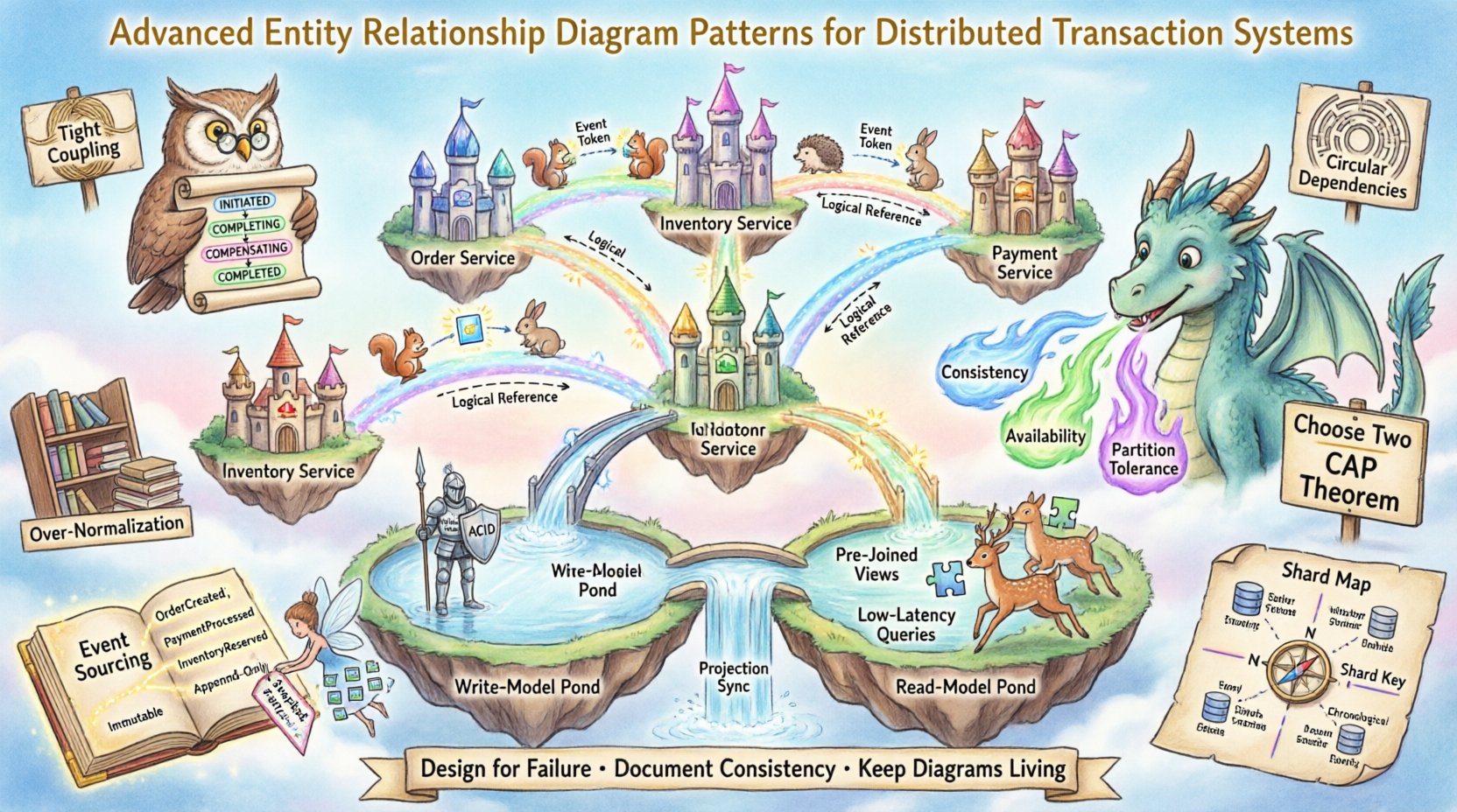
- Network Partitions: The CAP theorem dictates that in the event of a network split, you must choose between Consistency and Availability.
- Data Ownership: Services must own their data to prevent tight coupling. This limits direct foreign key relationships across service boundaries.
- Transaction Boundaries: Global transactions spanning multiple databases are generally discouraged due to performance and reliability risks.
When creating an ERD for this environment, the diagram must reflect logical relationships rather than just physical constraints. The visual representation needs to communicate where data lives and how it is synchronized.
🔗 Managing Referential Integrity Without Foreign Keys
In a distributed transaction system, physical foreign keys are often absent. Instead, logical relationships are enforced through application logic or asynchronous events. The ERD must capture these logical links clearly.
1. Logical Identifier References
Instead of a physical key constraint, models use unique identifiers. When drawing the diagram, indicate that a relationship is a logical link.
- Use dashed lines to represent logical dependencies.
- Label the relationship as “Reference” rather than “Constraint”.
- Specify the data type of the ID to ensure type safety in the schema.
2. Soft Referencing
Hard deletes are risky in distributed systems. A common pattern involves marking records as deleted rather than removing them. The ERD should include a status field.
- Include an
is_activeorstatuscolumn. - Document the lifecycle of the entity within the diagram notes.
- Clarify how orphaned records are handled during a deletion event.
3. Eventual Consistency Modeling
When data is replicated across services, consistency is not immediate. The ERD should visualize the replication lag.
- Mark entities that are read-only replicas.
- Distinguish between the “Source of Truth” and the “Cached Version”.
- Indicate the mechanism used to synchronize changes (e.g., Change Data Capture).
⚡ Modeling the Saga Pattern
The Saga pattern is a cornerstone of distributed transactions. It manages long-running operations by breaking a transaction into a sequence of local transactions. Each local transaction updates data within a specific service and triggers the next step.
1. Representing State Machines
Since Sagas rely on state, the ERD must explicitly model the state transitions of the process.
- Create a
SagaInstanceentity. - Define states such as
INITIATED,COMPLETING,COMPENSATING, andCOMPLETED. - Link the Saga Instance to the specific business entities it affects.
2. Compensating Transactions
If a step fails, the Saga must roll back previous steps. The diagram should show the inverse relationships.
- Document the compensating action for each step.
- Ensure the
SagaLogtable captures the history of all steps. - Visualize the rollback path as a separate relationship line.
3. Event Triggers
Sagas are often event-driven. The ERD needs to show how events trigger state changes.
- Include an
EventLogtable. - Map events to the specific Saga state transitions.
- Indicate which services consume which events.
📊 Comparing Consistency Patterns
Understanding the trade-offs between different consistency models is vital for accurate ERD design. The table below outlines the characteristics of common patterns.
| Pattern | Consistency Level | ERD Complexity | Best Use Case |
|---|---|---|---|
| Two-Phase Commit | Strong | Low | Internal service coordination |
| Saga Orchestration | Eventual | High | Long-running business processes |
| Saga Choreography | Eventual | Medium | Loosely coupled microservices |
| CQRS Read Model | Eventual | Medium | High-read workloads |
| Event Sourcing | Strong (Per Aggregate) | High | Audit trails and state reconstruction |
🔄 Command Query Responsibility Segregation (CQRS)
CQRS separates the read and write models. This means the ERD for the write side will differ significantly from the ERD for the read side.
1. Write Model Design
The write model focuses on data integrity and business rules.
- Normalize data to reduce redundancy.
- Enforce strict validation rules on creation.
- Keep the schema rigid to prevent logical errors.
2. Read Model Design
The read model focuses on performance and query speed.
- Denormalize data to avoid joins.
- Include pre-joined fields for common queries.
- Structure tables based on UI requirements rather than logic.
3. Synchronization Mechanism
The ERD must show how the write model updates the read model.
- Use projection entities to map the flow.
- Document the delay between write and read availability.
- Include a reconciliation process for data drift.
🗂️ Sharding and Partition Keys
Scaling often requires sharding data across multiple nodes. The ERD must reflect how data is distributed to ensure efficient querying.
1. Identifying the Shard Key
The shard key determines which node holds the data.
- Mark the shard key clearly in the entity definition.
- Ensure the key is frequently used in queries.
- Avoid keys that lead to skewed data distribution.
2. Cross-Shard Relationships
Relationships spanning shards are expensive. The ERD should highlight these.
- Use specific notation for cross-shard links.
- Minimize the number of relationships that cross shard boundaries.
- Consider denormalization to avoid cross-shard joins.
3. Global vs. Local Indexes
Indexing strategies differ based on the sharding model.
- Local indexes are efficient for single-shard queries.
- Global indexes require scanning all shards, impacting performance.
- Document which indexes are local and which are global.
📜 Event Sourcing and Immutable State
Event sourcing stores the state of an entity as a sequence of events. This changes how the ERD represents the entity itself.
1. The Event Store
The primary entity becomes the Event Log.
- Create an
EventStreamtable. - Store metadata such as
event_id,timestamp, andaggregate_id. - Ensure the payload is stored as structured data.
2. Aggregates
Aggregates are the root entities that trigger events.
- Link the Aggregate ID to the Event Stream.
- Do not store the current state as a column.
- Reconstruct state by replaying events from the log.
3. Snapshotting
To optimize performance, snapshots of the current state can be stored.
- Create a
Snapshottable. - Link the snapshot to the Aggregate ID.
- Document the version number for the snapshot.
🛡️ Common Pitfalls and Anti-Patterns
Even with advanced patterns, mistakes can occur. Recognizing anti-patterns helps maintain system health.
- Tight Coupling: Avoid referencing entities from other services directly. Use IDs instead.
- Circular Dependencies: Ensure Entity A does not depend on Entity B if Entity B depends on Entity A.
- Over-Normalization: In read-heavy systems, normalize too much, and performance suffers.
- Ignoring Timezones: Distributed systems operate globally. Store timestamps in UTC.
- Missing Idempotency: Ensure operations can be retried without side effects.
🔄 Schema Evolution and Versioning
Distributed systems evolve faster than monoliths. The ERD must support schema changes without breaking existing services.
1. Backward Compatibility
Changes to the schema must not break consumers.
- Only add fields, never remove or rename existing ones immediately.
- Deprecate fields gradually over time.
- Version the API contracts alongside the schema.
2. Migration Strategies
Handling data migration in production requires care.
- Use expand and contract patterns for deployment.
- Ensure the old schema remains readable during the transition.
- Document the rollback plan for failed migrations.
🖼️ Visualizing Cross-Service Dependencies
A standard ERD shows tables within one database. A distributed ERD must show services.
1. Service Boundaries
Group tables by the service that owns them.
- Use distinct containers for each service.
- Label the container with the service name.
- Show data flow between containers using arrows.
2. Data Flow
Indicate how data moves between services.
- Use solid lines for synchronous calls.
- Use dashed lines for asynchronous events.
- Label the direction of data flow.
3. Integration Points
Identify where services interact.
- Highlight API gateways in the diagram.
- Mark message brokers as intermediaries.
- Document the protocol used for each integration.
🏁 Final Considerations for System Designers
Designing for distributed transactions is an exercise in managing complexity. The ERD is a tool to communicate this complexity to the team. It should not just show tables; it should show the logic of the system.
- Focus on logical relationships over physical constraints.
- Document the consistency guarantees for every relationship.
- Plan for failure scenarios in the data model.
- Keep the diagram updated as the system evolves.
By following these patterns, you create a blueprint that supports high availability and data integrity. The diagram becomes a living document that guides development and maintenance.