Software architecture diagrams often become outdated shortly after creation. This phenomenon, known as documentation rot, creates a gap between the written plan and the actual system. Teams spend hours manually updating diagrams only to find them stale again by the next sprint. The C4 Model offers a structured approach to visualizing software architecture, but relying on manual drawing tools for every change is unsustainable at scale. Automation bridges this gap. By integrating generation processes into the development lifecycle, organizations maintain accurate, up-to-date visual documentation without sacrificing engineering velocity.
This guide explores practical strategies for automating the creation and maintenance of C4 Model diagrams. We focus on the mechanics of extraction, integration, and validation, ensuring that documentation remains a living artifact of the codebase rather than a static burden.
Understanding the C4 Model Automation Needs 🧩
The C4 Model structures architecture documentation into four hierarchical levels. Each level serves a different audience and requires different data sources. Automating this model requires understanding what data drives each layer.
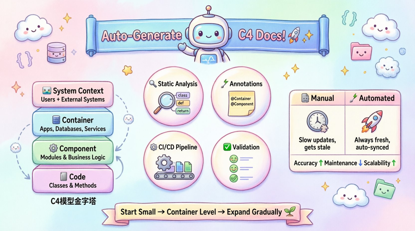
- System Context Diagram 🌍: Shows the software system and its users. This requires high-level metadata about the product scope and external dependencies.
- Container Diagram 📦: Displays high-level technology choices and data flow between containers. This needs information about deployment units and runtime environments.
- Component Diagram ⚙️: Breaks down containers into logical components. This requires source code structure analysis to identify classes, modules, and interfaces.
- Code Diagram 💻: Shows the relationship between classes and methods. This demands deep static analysis of the codebase.
Automation strategies vary significantly depending on which level you are targeting. Context diagrams are easier to generate from configuration files, while code diagrams require complex parsing logic. Attempting to automate all levels simultaneously can introduce noise. It is often more effective to prioritize the Container and Component levels first, as these provide the highest return on investment for most teams.
Strategy 1: Static Code Analysis and Parsing 🔍
The most robust method for automating architecture documentation relies on static analysis. This involves reading source code without executing it to build an abstract syntax tree (AST). From the AST, we can extract relationships such as inheritance, dependency, and method calls.
Extracting Component Relationships
To generate component diagrams automatically, the system must identify logical groupings within the code. This can be achieved through:
- Package/Module Naming Conventions: Analyze directory structures to infer container boundaries. A folder named
billinglikely represents a container or a major component. - Dependency Injection Containers: Many modern frameworks rely on configuration files to wire components. Parsing these configuration files reveals the dependency graph without needing to compile the application.
- Interface Implementation: Identify classes that implement specific interfaces. This helps in defining the component boundaries more accurately than file structure alone.
Handling Abstraction Leaks
A common challenge in code-based diagram generation is abstraction leaks. This occurs when the visual representation shows internal implementation details that should be hidden. For example, a component diagram should show that a PaymentService uses a DatabaseConnector, not that it calls a specific private method within a third-party library.
To mitigate this, automation logic must define filtering rules. These rules exclude:
- Standard library imports.
- Generated code (such as boilerplate from ORM tools).
- Internal helper classes that do not represent business logic.
By applying these filters, the generated diagrams remain high-level and readable, preserving the intent of the C4 Model.
Strategy 2: Annotation and Metadata Driven Generation 📝
While static analysis is powerful, it cannot always capture the business intent behind the code. Sometimes, a class is named OrderProcessor, but it handles Refunds as well. The code structure alone does not explain the boundary.
Annotations allow developers to explicitly mark architectural elements. This approach combines human intent with automated rendering.
Defining Architectural Boundaries
Developers can add metadata tags to classes or modules to define their role in the C4 hierarchy. For instance, a specific tag might indicate that a class belongs to the Container level. This metadata can be stored in comments, configuration files, or specific language-agnostic attributes.
Benefits of this approach include:
- Explicit Intent: The diagram reflects how the team views the system, not just how the compiler sees it.
- Reduced Noise: Developers can tag unused internal classes to hide them from the generated view.
- Rapid Updates: When a component changes, updating the annotation is faster than rewriting a diagram file.
Mapping Annotations to Diagrams
The automation pipeline reads these annotations to populate the diagram nodes. A mapping layer translates the code metadata into diagram-specific properties like labels, shapes, and colors. This ensures consistency across the documentation set.
| Annotation Type | C4 Level | Example Usage |
|---|---|---|
@SystemContext |
Context | Marking the root entry point of the application. |
@Container |
Container | Identifying web servers, databases, or microservices. |
@Component |
Component | Grouping related business logic classes together. |
@Code |
Code | Flagging specific classes for detailed class diagrams. |
Strategy 3: CI/CD Pipeline Integration ⚙️
Documentation automation fails if it sits outside the deployment pipeline. If developers do not see the results of their changes immediately, they will ignore the documentation. Integrating generation into the Continuous Integration (CI) process ensures that diagrams are always in sync with the code.
The Generation Trigger
The automation process should trigger on specific events. Common triggers include:
- Code Push: Run generation after every commit to catch immediate drift.
- Pull Request: Generate diagrams on merge requests to allow reviewers to verify architectural changes.
- Scheduled Job: Run nightly to catch drift caused by manual configuration changes.
Artifact Publishing
Once generated, the diagrams must be stored and versioned. The pipeline should output the diagrams as static files (like PNG or SVG) and store them in a repository or artifact storage. This allows the documentation to be linked from the project’s README or internal wiki.
Automated publishing ensures that:
- There is a single source of truth for the diagrams.
- Old versions of diagrams are archived but not lost.
- Access control can be managed centrally.
Strategy 4: Validation and Quality Control ✅
Automated generation does not guarantee correctness. A script can create a diagram that accurately reflects the code but is architecturally unsound. For example, the code might have a circular dependency that the diagram reveals clearly.
Automated Linting for Diagrams
Just as code has linters, diagrams can have rules. Validation scripts can check the generated output against architectural standards. Common checks include:
- Dependency Rules: Ensure that the
Backendcontainer does not depend directly on theFrontendcontainer. - Naming Consistency: Verify that container names match the defined naming conventions.
- Completeness: Check that every public API endpoint is represented in the Context diagram.
Human-in-the-Loop Reviews
Automation handles the bulk of the work, but human oversight remains essential. Teams should review the generated diagrams during architecture design meetings. This shifts the focus from drawing lines to discussing the implications of the connections shown.
This hybrid approach prevents the “black box” syndrome where developers trust the diagram blindly without understanding the underlying structure.
Comparing Manual vs. Automated Approaches 📊
To understand the value of automation, we must compare the effort and accuracy of manual versus automated documentation.
| Aspect | Manual Approach | Automated Approach |
|---|---|---|
| Accuracy | High initially, degrades quickly over time. | Consistently high, reflects current code state. |
| Maintenance Cost | High. Requires dedicated time for updates. | Low. Updates happen automatically on code change. |
| Scalability | Poor. Difficult to manage large codebases. | High. Scales with the number of repositories. |
| Consistency | Low. Varies by author and tool. | High. Enforced by templates and styles. |
| Feedback Speed | Slow. Changes are visible only after manual update. | Fast. Immediate feedback during development. |
Addressing Common Challenges 🛑
Implementing automation is not without friction. Teams often encounter specific hurdles that can derail the process.
Handling Dynamic Behavior
Static analysis cannot see runtime behavior. A microservice might dynamically load plugins that are not visible in the source code. To address this, teams can supplement static analysis with runtime tracing. By instrumenting the application, the system can log dependencies as they are loaded, which can then be fed back into the documentation generation process.
Managing Polyglot Environments
Modern systems often use multiple programming languages. A single automation tool might not support all of them equally. The solution is to adopt a unified intermediate representation (IR). Each language parser converts its code into the IR, and the diagram generator reads from the IR. This decouples the parsing logic from the visualization logic.
Version Control for Diagrams
If diagrams are generated, should they be committed to the repository? This is a debate within the community. Committed diagrams allow for better code review and version history but can cause merge conflicts. Stored diagrams (generated on the fly) avoid conflicts but require the build environment to be available to view them. A hybrid approach is often best: store the source annotations and configuration, but generate the images for viewing.
Maintenance and Evolution of the System 🔄
Once the automation is in place, the focus shifts to maintaining the quality of the generation logic. The rules that filter code or map annotations will change as the codebase evolves.
- Regular Audits: Schedule quarterly reviews of the generation rules to ensure they haven’t become obsolete.
- Feedback Channels: Allow developers to flag incorrect diagrams directly. This creates a feedback loop for improving the automation scripts.
- Documentation Standards: Update the team’s coding standards to align with the diagram requirements. For example, if a new package naming convention is needed for the diagrams, it should be part of the coding guidelines.
By treating the automation itself as software, teams can apply the same rigor to the documentation pipeline as they do to the application code.
The Impact on Technical Debt 📉
One of the most significant benefits of automated architecture documentation is the reduction of technical debt. When documentation is accurate, architects can make better decisions. They can see the true impact of a change before writing a single line of code.
Furthermore, automated diagrams make it easier to identify legacy code. If a diagram shows a component that has not been updated in years, it stands out visually. This visual cue can trigger refactoring initiatives without needing a deep code search.
Accurate documentation also aids in onboarding new team members. Instead of asking senior engineers how the system works, new hires can review the generated diagrams to understand the high-level architecture. This reduces the cognitive load on the team and accelerates productivity.
Final Thoughts on Implementation 🚀
Automating architecture documentation is not about replacing human understanding with machines. It is about removing the friction that prevents teams from keeping their knowledge up to date. By leveraging static analysis, annotations, and CI/CD integration, organizations can maintain a living map of their systems.
The key to success lies in starting small. Begin with the Container level, integrate with the pipeline, and validate the results. As the process proves its value, expand to Component and Code levels. Over time, the documentation becomes a reliable asset that supports rather than hinders development.
Remember that the goal is clarity. Whether manual or automated, the diagram must communicate the architecture effectively. If the automation produces a mess, it is better to pause and refine the rules than to push inaccurate data. With the right strategies, architecture documentation becomes a seamless part of the engineering culture.