Software architecture documentation often becomes a casualty of speed. In fast-moving development environments, the pressure to ship features frequently outweighs the need to maintain up-to-date visual representations of the system. However, stale documentation creates technical debt that is often harder to repay than code debt. The C4 Model offers a structured approach to documenting software architecture at different levels of abstraction. Integrating this model into continuous integration (CI) pipelines ensures that architecture documentation evolves alongside the codebase, maintaining clarity and reducing drift.
This guide explores how to treat architecture diagrams as code. By embedding C4 practices into your build process, you create a feedback loop where documentation is validated, versioned, and deployed just like your application logic. This approach reduces the risk of miscommunication between teams and ensures that new developers can onboard quickly with accurate visual references.
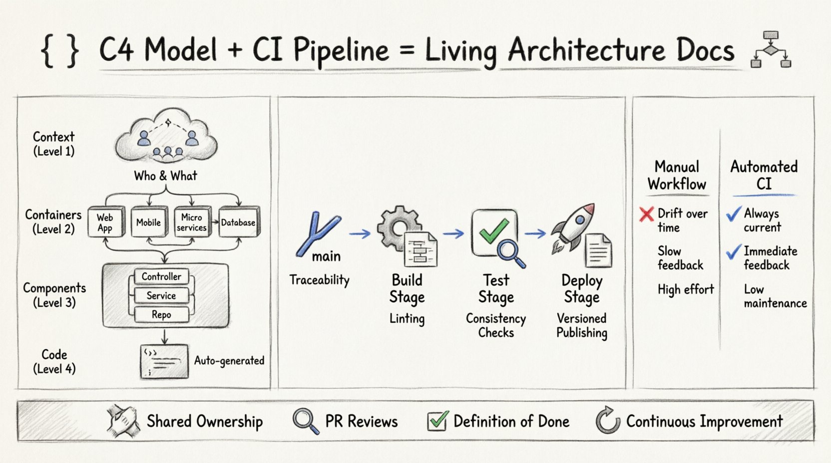
Understanding the C4 Model Layers 📐
Before automating the process, it is essential to understand the four levels of the C4 model. Each level serves a specific audience and requires different maintenance strategies within a pipeline.
- Context (Level 1): Provides a high-level view of the system, its users, and external dependencies. It answers the question: What does this system do, and who uses it? This diagram is crucial for stakeholder alignment and should be updated whenever a new external service is integrated.
- Containers (Level 2): Breaks the system down into individual run-time environments. This includes web applications, mobile apps, microservices, and databases. This view is vital for infrastructure teams and helps in understanding deployment topology.
- Components (Level 3): Details the logical building blocks within a container. This level describes the internal structure of a service, such as controllers, repositories, and business logic. It is primarily for developers working on the specific service.
- Code (Level 4): This level is rarely visualized in the same way. It refers to the class or method-level structure. While often generated automatically from source code, keeping this in sync with C4 documentation requires strict naming conventions and automated extraction tools.
The Problem with Manual Documentation 🛑
Traditional documentation workflows rely on manual updates. A developer creates a diagram, saves it, and moves on. Over time, as the code changes, the diagram becomes inaccurate. This leads to:
- Architecture Drift: The actual system no longer matches the documented design.
- Onboarding Friction: New team members must reverse-engineer the system because the diagrams are outdated.
- Review Bottlenecks: Architecture reviews become discussions about whether the diagram matches reality rather than evaluating the design itself.
- Lost Knowledge: When a team member leaves, the context of their design decisions is lost if not documented in a persistent, versioned manner.
Automating these processes through CI pipelines mitigates these risks. It shifts the burden from manual maintenance to automated validation.
Integrating C4 into the CI Pipeline 🔗
Embedding C4 practices requires a shift in how documentation is treated. It should not be an afterthought; it should be part of the definition of done. The integration happens across various stages of the pipeline, ensuring that diagrams are generated, validated, and published automatically.
1. Version Control and Source of Truth
The first step is to store diagram definitions in the same version control system as the source code. This allows for:
- Traceability: You can see exactly which code change triggered a diagram update.
- Collaboration: Multiple team members can propose changes via pull requests.
- History: The git history serves as an audit trail of architectural evolution.
Using a domain-specific language or a structured text format for diagrams ensures that these files are readable and mergeable, unlike binary image files.
2. The Build Stage: Generation and Validation
During the build phase, the pipeline should automatically generate diagrams from the source definitions. This stage should include validation steps to ensure the diagrams are syntactically correct and logically consistent.
- Compilation: Convert the diagram definitions into visual formats (SVG, PNG).
- Linting: Check for naming conventions, correct relationship types, and missing components.
- Validation: Ensure that the diagram reflects the current codebase state. For example, if a component is removed in the code, the diagram should either be updated or flagged for review.
3. The Test Stage: Automated Consistency Checks
Automated tests can verify that the documentation matches the code. This is particularly effective for Level 3 (Component) diagrams. Static analysis tools can parse the code and compare the discovered components against the documented components.
- Coverage Checks: Ensure all public APIs are represented in the diagram.
- Dependency Checks: Verify that external dependencies listed in the diagram exist and are correctly versioned.
- Link Validation: Check that internal links within the documentation point to valid sections.
4. The Deploy Stage: Publishing and Distribution
Once the diagrams pass validation, they should be deployed to a documentation site or a shared artifact repository. This ensures that the documentation is always accessible and matches the deployed version of the software.
- Versioning: Store documentation alongside version tags. This allows users to view the architecture of version 1.0.0 alongside version 1.1.0.
- Access Control: Ensure that sensitive architectural details are only visible to authorized personnel.
- Update Notifications: Trigger notifications when architecture changes occur, keeping stakeholders informed.
Comparing Manual vs. Automated Workflows 📊
To understand the value of this integration, consider the following comparison of workflows.
| Feature | Manual Workflow | Automated CI Workflow |
|---|---|---|
| Accuracy | High initial effort, degrades over time | Maintained by code changes |
| Consistency | Dependent on individual discipline | Enforced by pipeline rules |
| Feedback Speed | Slow (post-release) | Immediate (during PR) |
| Maintainability | High effort | Low effort (once configured) |
| Versioning | Manual file management | Automatic via Git tags |
Strategies for Specific C4 Levels 🛠️
Different levels of the C4 model require different automation strategies within the pipeline.
Context Diagrams
These diagrams change less frequently but are critical for onboarding. Automation should focus on ensuring that new external systems are flagged for review. When a new dependency is added to the code, the pipeline can alert the architect to update the context diagram.
Container Diagrams
These are often tied to infrastructure-as-code. Automation can extract container definitions from deployment manifests (such as Kubernetes YAML files) and generate the container diagram automatically. This ensures the visual representation matches the deployment configuration exactly.
Component Diagrams
This is the most complex level to automate. It requires deep parsing of the source code. The pipeline should run static analysis tools to identify classes and methods, then map them to the component diagram. If the code structure diverges from the diagram, the build should fail, requiring a documentation update before merging.
Challenges and Solutions ⚠️
Implementing automated C4 practices is not without challenges. Teams often face resistance due to perceived overhead or complexity.
Challenge 1: Initial Configuration Time
Setting up the pipeline to understand the codebase and generate diagrams requires significant upfront effort. Teams may feel this slows down initial development.
- Solution: Start small. Automate Level 1 and Level 2 first. Level 3 can be added later. Prioritize critical services over legacy ones.
Challenge 2: False Positives in Validation
Automated checks might flag valid architectural changes as errors if the logic is too rigid.
- Solution: Tune the validation rules. Allow for manual overrides in specific cases, but require a comment explaining why the override was necessary.
Challenge 3: Tooling Complexity
Choosing the right tools to parse code and generate diagrams can be daunting.
- Solution: Use open standards where possible. Avoid proprietary formats that lock you into specific vendors. Focus on the text-based representation of the diagrams rather than the rendering engine.
Cultural Shifts Required 🧠
Technical implementation is only half the battle. Embedding C4 practices requires a shift in team culture.
- Shared Ownership: Documentation is not just for architects. Developers should feel responsible for keeping their component diagrams accurate.
- Pull Request Reviews: Architecture diagrams should be reviewed in pull requests just like code. If the code changes, the diagram must change.
- Definition of Done: Update the Definition of Done to include diagram updates. A feature is not complete until the relevant C4 diagrams are updated.
- Continuous Improvement: Regularly review the documentation process. Are the diagrams still useful? Are the automated checks too noisy? Adjust the workflow accordingly.
Measuring Success 📈
To ensure the integration is effective, track specific metrics. These metrics help identify areas where the process is breaking down.
- Documentation Coverage: What percentage of the codebase has associated diagrams?
- Update Frequency: How often are diagrams updated relative to code commits?
- Validation Errors: How many build failures are caused by diagram inconsistencies?
- Onboarding Time: Does the time it takes for new developers to become productive decrease over time?
- Drift Rate: How much time passes between a code change and a corresponding diagram update?
Handling Legacy Systems 🏛️
Not all systems are built with automation in mind. Legacy systems often lack the structure required for automatic diagram generation. For these systems, a hybrid approach is necessary.
- Incremental Migration: Start by documenting the Context and Container levels. These provide the most value with the least effort.
- Manual Entry with Validation: Maintain diagrams manually but use the pipeline to validate that the code structure matches the diagram descriptions.
- Strangler Fig Pattern: As new features are added, document them in the new C4-compliant way. Gradually replace the old documentation as the system evolves.
The Role of Pull Requests 🔄
Pull requests are the natural place to enforce C4 practices. They provide a mechanism for review and collaboration.
- Diagram Changes: Any change to a diagram file should trigger a review. Reviewers can check if the diagram accurately reflects the code changes.
- Comments: Use comments to discuss architectural decisions. This creates a historical record of why certain design choices were made.
- Blocking Rules: Configure the pipeline to block merges if diagram validation fails. This ensures that the documentation is never left behind.
Conclusion 🎯
Embedding the C4 model into continuous integration pipelines transforms documentation from a static burden into a dynamic asset. It aligns the documentation lifecycle with the code lifecycle, ensuring that the system description is always current. While the initial setup requires investment, the long-term benefits in terms of reduced drift, faster onboarding, and clearer communication are significant.
By treating diagrams as code, teams can leverage the same automation tools that they use for software delivery. This creates a unified workflow where quality is enforced automatically, and architecture remains a living part of the development process. The goal is not perfection, but consistency. With the right pipeline integration, architecture documentation becomes a reliable source of truth that supports the entire development lifecycle.