


💡 Key Takeaways
- Standardize Notation: Use consistent shapes and symbols across all diagrams to prevent misinterpretation.
- Naming Conventions: Adopt strict naming rules for elements to ensure clarity and searchability within models.
- Layout Discipline: Maintain uniform spacing and alignment to enhance visual flow and reduce cognitive load.
- Relationship Clarity: Define precise rules for lines and arrows to accurately represent system connections.
In the realm of software architecture and system design, diagrams serve as the universal language. They bridge the gap between abstract concepts and concrete implementation. However, a diagram that lacks internal coherence becomes a source of confusion rather than clarity. Consistency is not merely an aesthetic preference; it is a fundamental requirement for professional modeling. When stakeholders, developers, and architects review a model, they rely on established patterns to extract meaning quickly. Deviating from these patterns introduces friction and potential errors.
This guide outlines the essential rules for maintaining consistency in Unified Modeling Language (UML) diagrams. These principles apply regardless of the tool used to create the visuals. The goal is to create documentation that is intuitive, maintainable, and precise.
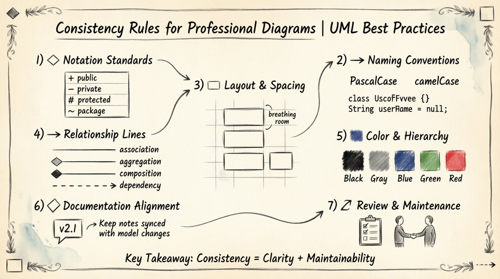
1. Notation Standards 🎨
The foundation of any professional diagram lies in adhering to the standard notation defined by the modeling community. While minor variations exist between tools, the core symbols for classes, interfaces, actors, and states remain constant. Deviating from these symbols creates ambiguity.
Class Diagram Symbols
When constructing class diagrams, strict adherence to rectangular shapes for classes is required. The box should be divided into three distinct sections: the class name, attributes, and operations. The name should always occupy the top section. Attributes and operations should be listed below, separated by a horizontal line.
- Public Members: Use the plus sign (+) prefix.
- Private Members: Use the minus sign (-) prefix.
- Protected Members: Use the hash sign (#) prefix.
- Package Scope: Use the tilde sign (~) prefix.
Do not mix these conventions within the same model. If a model uses the + symbol for public attributes, every class must follow this rule. Inconsistent visibility modifiers make it difficult to determine access levels at a glance.
Sequence Diagram Lifelines
In sequence diagrams, the representation of objects and participants must remain uniform. Lifelines are vertical dashed lines extending from the top of the diagram. Activation bars should be narrow rectangles placed on the lifeline during execution. Ensure the width of all activation bars is identical to maintain visual rhythm.
State Machine Diagrams
States should be represented as rounded rectangles. Transitions are solid lines with open arrowheads. Entry and exit points should be clearly marked with specific symbols (e.g., a filled circle for the initial state and a double circle for the final state). Mixing different shapes for the same type of state breaks the visual language.
2. Naming Conventions 🏷️
Naming is the most common source of inconsistency in modeling. Without strict rules, one architect might name a class User, while another uses Person. One might use saveRecord(), while another prefers persistData(). These variations force readers to constantly translate terminology, slowing down comprehension.
Class and Component Naming
Class names should follow a PascalCase convention. This means capitalizing the first letter of each word (e.g., CustomerOrder). Acronyms should be treated as single words (e.g., HTTPConnection rather than HttpConnection). This ensures that class names are easily distinguishable from variable names, which typically use camelCase.
Attribute and Method Naming
Attributes and methods should use camelCase. The first letter of the name is lowercase, and subsequent words are capitalized (e.g., calculateTotal()). This distinction helps in reading the diagram textually.
| Element Type | Convention | Example |
|---|---|---|
| Class | PascalCase | PaymentGateway |
| Attribute | camelCase | transactionId |
| Method | camelCase | processRefund() |
| Interface | Prefixed by I | IPaymentProcessor |
Namespace and Package Structure
When organizing models into packages or namespaces, the hierarchy should reflect the logical domain of the system. Avoid deep nesting beyond three levels. Use lowercase names for packages to distinguish them from classes. For example, com/company/project is standard, whereas com.Company.Project can create confusion regarding whether the text represents a package or a class.
3. Layout and Spacing 📏
A cluttered diagram is a failed diagram. Consistency in layout ensures that the viewer can scan the information efficiently. This involves alignment, spacing, and grouping.
Grid Alignment
Use an invisible grid to align elements. Rectangles representing classes or components should be aligned either horizontally or vertically. Do not place elements at arbitrary angles unless specifically required to indicate a specific relationship direction. Vertical stacking is generally preferred for related components.
Spacing Rules
Maintain uniform gaps between elements. If the distance between two classes is 50 pixels in one area, it should be similar in other areas. This creates a “visual breathing room” that prevents the diagram from appearing cramped. Consistent spacing also helps in identifying clusters of related functionality.
Grouping and Frames
Use frames to group related diagrams or components. A frame should encompass all elements belonging to a specific subsystem. The border of the frame should be solid, and the label should be placed at the top left corner. Ensure that frames do not overlap with elements outside their designated scope.
4. Relationship Lines and Arrows ➡️
The connections between elements are as important as the elements themselves. Misrepresenting a relationship can lead to incorrect assumptions about system behavior.
Association vs. Aggregation
Distinguish clearly between associations and aggregations. An association is a simple line. An aggregation (a “has-a” relationship where the parts can exist independently) uses an empty diamond at the source end. A composition (a “owns-a” relationship where parts cannot exist without the whole) uses a filled diamond. Do not use empty and filled diamonds interchangeably for different types of relationships.
Dependency Lines
Dependencies should be represented by dashed lines with open arrowheads. These indicate that one element relies on another. Avoid using solid lines for dependencies, as this implies a stronger structural link. Ensure that the arrowhead points to the element being depended upon.
Multiplicity
Multiplicity values (e.g., 1, 0..1, *) should be placed near the end of the line closest to the class they describe. If multiple multiplicities are shown, ensure they are formatted consistently. Do not omit multiplicity where it is required, and do not add it where it is implied.
5. Color and Hierarchy 🎨
Color should be used sparingly to convey meaning, not for decoration. Overusing color confuses the hierarchy. If every class is a different color, the eye has nothing to focus on.
Standard Color Palette
Adopt a minimal palette. For example:
- Black or Dark Gray: Standard elements.
- Blue: Interface or abstract classes.
- Green: Active or running processes.
- Red: Error states or critical warnings.
Do not apply colors randomly. If a class is blue, it must represent an interface or abstract concept across the entire model. If a state is red, it must indicate an error state consistently.
Font Consistency
Use a single sans-serif font throughout the model. Common choices include Arial, Helvetica, or Roboto. The font size should be legible but uniform. Class names should be bold, while attributes and methods should be regular weight. This visual distinction allows for quick scanning of the diagram content.
6. Documentation Alignment 📝
A diagram is only as good as its accompanying documentation. Inconsistencies between the visual model and the text description are a major source of technical debt.
Version Control
Ensure that the version number on the diagram matches the version of the system documentation. If the code changes, the diagram must be updated. A diagram showing a feature that was removed is misleading. Establish a rule where diagram updates are part of the code review process.
Contextual Notes
Use notes to explain complex logic that cannot be represented by standard symbols. These notes should be attached to specific elements using dashed lines. Ensure that note text is concise. Long paragraphs inside a diagram box reduce readability. If a note exceeds three lines, consider creating a separate specification document and referencing it.
7. Review and Maintenance 🔄
Consistency is not a one-time setup; it is an ongoing practice. Regular reviews are necessary to ensure standards are maintained as the system evolves.
Automated Checks
Where possible, use tools that validate model consistency. Automated checks can verify that all classes follow naming conventions or that all relationships have defined multiplicities. This reduces the manual effort required to maintain quality.
Peer Review
Incorporate diagram reviews into the development workflow. Peers should check for adherence to the established rules. This creates a shared understanding of the model across the team. If a rule is unclear, update the style guide rather than allowing exceptions.
Conclusion 🏁
Maintaining consistency in UML diagrams requires discipline and a clear set of rules. By standardizing notation, naming, layout, relationships, and color, teams can create models that serve as reliable documentation. These diagrams become a shared asset that accelerates development and reduces errors. The effort invested in consistency pays off in reduced communication overhead and higher quality system designs.
Apply these rules rigorously from the first sketch to the final delivery. A professional diagram is a testament to a professional engineering process.