


💡 Key Takeaways
- Visualizing Logic: State machine diagrams provide a clear visual representation of object lifecycles and behavior over time.
- State Management: They define specific conditions (states) and the rules (transitions) governing movement between them.
- Event-Driven: Changes occur only when specific events trigger a transition, ensuring controlled system responses.
- Concurrency: Orthogonal regions allow modeling of multiple independent behaviors occurring simultaneously within a single state.
In the realm of Unified Modeling Language (UML), few diagrams offer as much precision for dynamic systems as the state machine diagram. While class diagrams describe structure and sequence diagrams describe interaction flow, state machine diagrams focus on the life history of an individual object. They answer critical questions: How does this component behave over time? Under what conditions does it change? What happens when an unexpected event occurs?
Understanding these diagrams is essential for system architects and developers working on reactive systems, embedded software, or complex business workflows. This guide explores the mechanics, advanced features, and practical applications of state machine modeling without relying on specific tools or vendors.
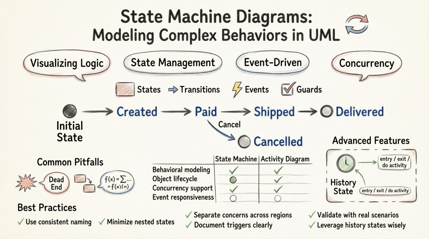
Core Components of a State Machine 🏗️
A state machine diagram is composed of several fundamental elements. Each element serves a specific purpose in defining the behavior of the system. Mastering these components allows for the construction of robust behavioral models.
States
A state represents a condition or situation during the life of an object in which it can perform an activity or wait for an event. States are depicted as rounded rectangles. There are several types of states:
- Initial State: Represented by a solid black circle, this marks the starting point of the state machine.
- Final State: Represented by a solid black circle within a circle, this indicates the termination of the state machine.
- Simple State: A state with no internal structure.
- Composite State: A state that contains substates. This allows for hierarchy and complexity within a single state.
- Submachine State: A state that invokes another state machine diagram, promoting reuse.
Transitions
Transitions define the movement from one state to another. They are triggered by events and may include conditions and actions. Visually, a transition is an arrow pointing from the source state to the target state.
Events
An event is a significant occurrence that triggers a transition. Events can be:
- Signal Events: Asynchronous communications.
- Call Events: Synchronous method invocations.
- Change Events: Boolean expressions that become true.
- Time Events: Conditions based on time duration or specific clock times.
Actions and Guards
When a transition occurs, actions may be executed. These are denoted by the keyword action. A guard condition is a boolean expression enclosed in square brackets [condition]. The transition only occurs if the guard evaluates to true. If multiple transitions are possible, the first one with a true guard is taken.
Advanced Modeling Techniques 🧠
As systems grow in complexity, basic states and transitions are often insufficient. Advanced features allow for more nuanced modeling of real-world scenarios.
Orthogonal Regions
Complex objects often exhibit multiple behaviors simultaneously. Orthogonal regions allow a composite state to be partitioned into independent submachines. For example, a Phone state might have one region for Ringing and another for Charging. These regions operate concurrently, meaning the phone can ring while charging. This is represented by a dashed line dividing the composite state.
History States
History states preserve information about the state of a composite state when it is exited and re-entered. There are two types:
- Deep History: Remembered the last active substate.
- Shallow History: Remembered the last active top-level substate.
This is crucial for user interfaces or workflows where returning to a complex screen should restore the previous context without reinitializing the entire flow.
Entry, Exit, and Do Activities
Within a state, specific activities can be triggered:
- Entry: Executed once upon entering the state.
- Exit: Executed once upon leaving the state.
- Do: Executed continuously while the state is active. This is useful for polling, monitoring, or maintaining a loop.
State Machine vs. Activity Diagrams ⚖️
Selecting the right diagram type is vital. While both model behavior, they serve different purposes. The following table clarifies when to use each.
| Feature | State Machine Diagram | Activity Diagram |
|---|---|---|
| Focus | Object lifecycle and reactivity | Workflow and control flow |
| Trigger | Events trigger transitions | Completion of previous activity triggers next |
| Concurrency | Orthogonal regions | Fork/Join bars |
| Best For | Embedded systems, protocols | Business processes, algorithms |
Design Patterns and Implementation 🛠️
Implementing state machines in code requires careful planning to avoid spaghetti logic. Several patterns facilitate this.
The State Pattern
In object-oriented programming, the State pattern allows an object to change its behavior when its internal state changes. Each state is represented by a class. This encapsulates state-specific logic, making the main class simpler.
Table-Driven State Machines
For simpler systems, a lookup table can define transitions. The current state and the event act as keys to determine the next state and the action to perform. This approach is highly efficient for parsing or protocol handling.
Common Pitfalls to Avoid ⚠️
Even experienced modelers can fall into traps. Keeping these common issues in mind improves the quality of the diagram.
- State Explosion: Creating too many states makes the diagram unreadable. Use composite states to group related behaviors.
- Unreachable States: Ensure every state can be reached from the initial state. Dead ends confuse maintainers.
- Missing Transitions: Define behavior for all events. What happens if an event occurs in an unexpected state? Use a default or error state.
- Complex Guards: Avoid overly complex guard conditions. If a condition is too hard to read, consider breaking the logic into separate states.
Practical Example: Order Processing 🛒
Consider an e-commerce order system. The order object moves through several states:
- Created: The order is saved but not confirmed.
- Paid: Payment is verified.
- Shipped: Goods are dispatched.
- Delivered: The customer receives the item.
- Cancelled: The process is terminated.
Transitions are triggered by events like ConfirmPayment, ShipOrder, or RequestCancel. Guard conditions ensure an order cannot be shipped before payment is confirmed. A Do activity might monitor for payment status while in the Created state.
Conclusion and Best Practices ✅
State machine diagrams are powerful tools for capturing the dynamic behavior of software components. They provide a rigorous way to define how a system reacts to stimuli over time. By adhering to standard UML notation and focusing on clarity, teams can reduce ambiguity in system requirements.
When modeling, prioritize readability. A diagram that is easy to understand is more valuable than one that is technically perfect but confusing. Use composite states to manage complexity and leverage history states to preserve context. Regularly review these diagrams with stakeholders to ensure they align with actual business needs.
Effective modeling leads to more reliable code. When the design is clear, the implementation follows naturally, reducing bugs and maintenance costs. Whether designing a traffic light controller or a customer portal, state machines offer a structured path to complex behavior.