


💡 Key Takeaways
Visual Clarity: Reverse engineering transforms dense source code into readable UML diagrams, revealing hidden architecture.
Dependency Mapping: Automated analysis identifies relationships between modules, aiding in refactoring and understanding coupling.
Legacy Modernization: Creating diagrams from existing codebases bridges the gap between technical debt and future documentation.
In the landscape of software development, maintaining documentation often falls behind the pace of implementation. Codebases grow, features are added, and original architectural decisions become obscured. This is where reverse engineering becomes an essential discipline. It involves analyzing existing source code to reconstruct a visual representation, typically using Unified Modeling Language (UML) diagrams. This process does not merely document what exists; it clarifies how components interact, where dependencies lie, and how the system is structured.
Understanding Reverse Engineering in the Context of UML 🧩
Reverse engineering in software development is the process of analyzing a system to identify its components and their interrelationships. When applied to UML, the goal is to derive a diagrammatic representation from the actual implementation. Unlike forward engineering, where diagrams guide the writing of code, reverse engineering starts with the code and derives the diagrams.
This approach is particularly valuable for legacy systems where documentation may be outdated or non-existent. By parsing the source code, tools can extract class names, method signatures, inheritance hierarchies, and association links. These elements form the building blocks of class diagrams, sequence diagrams, and component diagrams.
The Core Objective
The primary objective is to achieve a state of understanding. Developers often encounter legacy code that feels like a black box. Reverse engineering opens this box, allowing teams to visualize the data flow and structural logic without needing to read every line of implementation. It serves as a bridge between the concrete reality of code and the abstract conceptualization of design.
Why Generate Diagrams from Code? 📊
There are several strategic reasons to undertake this process. It is not simply about creating pretty pictures; it is about risk reduction and clarity.
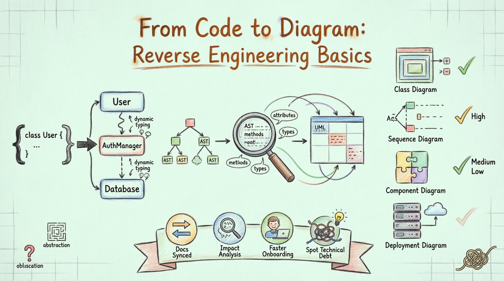
Documentation Synchronization: Code changes frequently. Diagrams generated from code are always up-to-date, reflecting the current state of the system.
Impact Analysis: Before refactoring a module, developers need to know what depends on it. Diagrams highlight these dependencies clearly.
Onboarding: New team members can grasp the system architecture much faster by reviewing diagrams than by navigating a repository of files.
Identifying Technical Debt: Complex structures often reveal themselves as tangled webs in diagrams, highlighting areas that need simplification.
The Process of Reverse Engineering 🔄
Transforming code into diagrams involves a systematic workflow. While specific implementations vary, the logical steps remain consistent across environments.
1. Parsing and Analysis
The first step involves reading the source code files. The system parses the syntax to understand the structure. It identifies classes, interfaces, functions, and variables. This phase converts raw text into a structured data format, often an Abstract Syntax Tree (AST). The parser must be language-aware to correctly interpret syntax specific to the programming language in use.
2. Extraction of Metadata
Once the code is parsed, the system extracts specific metadata. This includes:
Attributes: Data fields within classes.
Methods: Functions and their access modifiers (public, private, protected).
Types: The data types associated with attributes and return values.
Relationships: Inheritance (extends/implements), association (usage), and aggregation (composition).
3. Mapping to UML Semantics
The extracted metadata must be mapped to UML notation. For instance, a class definition maps to a Class Diagram box. A method call within a function maps to an interaction in a Sequence Diagram. This mapping requires logical inference. If class A creates an instance of class B, the system infers an association or dependency.
4. Visualization and Rendering
The final step is rendering the data into a visual format. This involves placing elements on a canvas and drawing lines to represent relationships. The layout algorithms attempt to organize the diagram so that it is readable, minimizing crossing lines and grouping related components.
Common Diagrams Generated 📝
Not all diagrams are equally suitable for reverse engineering. Some capture static structure, while others capture dynamic behavior.
Diagram Type | Focus | Utility in Reverse Engineering |
|---|---|---|
Class Diagram | Static Structure | High. Shows inheritance, attributes, and methods directly from code. |
Sequence Diagram | Dynamic Behavior | Medium. Requires tracing method calls to understand interaction flow. |
Component Diagram | System Modules | High. Groups classes into logical units or libraries. |
Deployment Diagram | Infrastructure | Low. Requires knowledge of server configuration, not just code. |
Challenges in the Process ⚠️
While powerful, reverse engineering is not without difficulties. Several factors can complicate the generation of accurate diagrams.
Abstraction and Hiding
Modern codebases rely heavily on abstraction. Interfaces and polymorphism can obscure the actual implementation. A method might be defined in an interface but implemented in multiple classes. Visualizing this requires showing both the contract and the realization, which can clutter a diagram.
Dynamic Typing
Languages that support dynamic typing (where variable types are determined at runtime) present a challenge for static analysis. The reverse engineering tool may struggle to determine the exact type of an object without executing the code or analyzing complex control flows.
Code Obfuscation
In some contexts, code is obfuscated to protect intellectual property. Minification and renaming of variables make the source code difficult for humans and machines to read. Reverse engineering obfuscated code requires significantly more sophisticated analysis techniques.
Complex Dependencies
Large systems often have circular dependencies or tightly coupled modules. When a diagram is generated, these dependencies can create a “spaghetti” effect, where lines cross chaotically. Manual intervention is often required to clean up the layout and group related elements logically.
Best Practices for Accuracy ✅
To ensure the generated diagrams are useful, certain practices should be followed during the reverse engineering process.
Filter Noise: Exclude standard libraries or boilerplate code that adds visual clutter without architectural value. Focus on custom business logic.
Group Modules: Use packages or namespaces to group classes. This prevents the diagram from becoming a single massive node.
Validate Relationships: Automated tools can sometimes misinterpret relationships. Review the generated links to ensure they accurately reflect the code logic.
Iterate: Reverse engineering is rarely a one-time task. As the codebase evolves, the diagrams should be regenerated and reviewed periodically.
The Role of Automation 🤖
Manual reverse engineering is impractical for large projects. Automation is key. Automated parsers scan repositories, build dependency graphs, and export to standard formats like XMI or PlantUML. This allows teams to integrate diagram generation into their CI/CD pipelines.
Automation ensures that documentation is never stale. If a developer commits a change that breaks a dependency, the diagram generation process can flag the inconsistency. This continuous validation helps maintain system integrity over time.
Integrating Diagrams into Maintenance 🛠️
Once diagrams are generated, they should be actively used. They are not just for presentation. Teams can use them to plan refactoring efforts. For example, if a class diagram shows a class with excessive dependencies, it is a candidate for decomposition.
Furthermore, diagrams help in code reviews. Reviewers can look at the structural impact of a proposed change before reading the diff. This shifts the focus from syntax to architecture, improving the quality of the codebase.
Conclusion on Structural Insight 🏁
Reverse engineering code into UML diagrams is a fundamental practice for maintaining complex software systems. It transforms opaque code into transparent architecture, enabling better decision-making and clearer communication. While challenges exist regarding dynamic typing and complex dependencies, the benefits of synchronized documentation outweigh the costs. By prioritizing structural clarity, teams can navigate legacy systems with confidence and modernize their applications with precision.