💡 Key Takeaways
- Definition Clarity: Understanding UML terms prevents miscommunication during development.
- Visual Standard: UML provides a universal language for modeling system architecture.
- Diagram Types: Distinguish between structural and behavioral diagrams for accurate design.
- Relationships: Master associations, aggregations, and inheritance to define connections.
Unified Modeling Language (UML) serves as the backbone for software system design. It offers a standardized way to visualize, specify, construct, and document the artifacts of a software system. Without a shared vocabulary, teams often face misunderstandings that lead to costly rework. This guide outlines the foundational terminology required to navigate system architecture effectively. By grasping these concepts, developers and stakeholders can align their vision before a single line of code is written.
Understanding the Core Structure 🏗️
UML is not merely a drawing tool; it is a language with grammar and syntax. To read it fluently, one must understand the two primary categories of diagrams: structural and behavioral. This distinction is crucial for organizing information correctly.
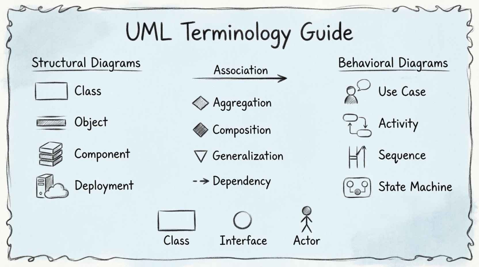
1. Structural Diagrams
Structural diagrams depict the static aspect of a system. They represent the physical or logical architecture, showing what the system consists of at a specific moment in time. These diagrams focus on objects, classes, interfaces, and their relationships.
- Class Diagram: The most common structural diagram. It displays classes, their attributes, operations, and the relationships between objects.
- Object Diagram: Shows a snapshot of the detailed state of a system at a particular time. It is an instance of a class diagram.
- Component Diagram: Describes the organization and dependencies between software components.
- Deployment Diagram: Visualizes the physical hardware and software environment, showing nodes and artifacts.
- Package Diagram: Groups elements into packages to organize complex models.
- Composite Structure Diagram: Illustrates the internal structure of a class or component.
2. Behavioral Diagrams
Behavioral diagrams illustrate the dynamic aspects of a system. They describe how the system behaves over time, including interactions between objects and state changes.
- Use Case Diagram: Represents the functional requirements of a system. It shows actors and the use cases they interact with.
- Activity Diagram: Similar to a flowchart, it models the flow of control or data from activity to activity.
- Sequence Diagram: Shows object interactions arranged in time sequence.
- Communication Diagram: Emphasizes the structural organization of objects that send and receive messages.
- State Machine Diagram: Models the different states an object can be in and the transitions between them.
- Interaction Overview Diagram: Combines activity and sequence diagrams to show high-level control flow.
- Timing Diagram: A specialized interaction diagram that focuses on time constraints.
Relationships and Connectors 🔗
One of the most critical areas of UML terminology involves the lines that connect elements. These lines define how entities relate to one another. Misinterpreting these relationships can lead to flawed system logic.
| Relationship | Description |
|---|---|
| Association | A structural relationship that describes a set of links between objects. |
| Aggregation | A special type of association representing a whole-part relationship where the part can exist independently. |
| Composition | A stronger form of aggregation where the part cannot exist without the whole. |
| Generalization | Represents inheritance, where a child class inherits features from a parent class. |
| Dependency | A relationship where a change in one element affects another. |
Key Notation Elements 📝
UML relies on specific symbols to convey meaning efficiently. Recognizing these symbols is essential for reading any diagram.
Classes and Objects
A class is represented by a rectangle divided into three compartments: the name, attributes, and operations. The name is bolded at the top. Attributes and operations are listed below, often with visibility indicators like + for public and - for private.
Interfaces
An interface is typically depicted as a circle or a rectangle with the keyword <<interface>> above the name. It defines a set of operations that a class must implement without specifying how they are implemented.
Actors
Actors represent users or external systems. They are drawn as a stick figure. Actors initiate interactions with the system, known as use cases.
Messages
In sequence diagrams, messages are arrows between objects. A solid line with a filled arrowhead indicates a synchronous call. A dashed line with an open arrowhead indicates a return message. A solid line with a filled block arrowhead indicates a signal.
Why Precision Matters in Modeling 🎯
Using correct terminology ensures that the design intent is preserved throughout the development lifecycle. When a developer reads a class diagram, they should immediately understand the responsibility of each component. Ambiguity in UML notation can lead to implementation errors that are expensive to fix later.
For instance, confusing aggregation with composition changes the lifecycle of an object. If a part is aggregated, it might exist in multiple wholes. If it is composed, it is destroyed when the whole is destroyed. This distinction impacts memory management and data integrity.
Similarly, understanding the difference between a sequence diagram and an activity diagram is vital. A sequence diagram focuses on the order of messages between objects. An activity diagram focuses on the flow of logic within a system. Choosing the wrong diagram type can obscure the intended behavior.
Common Pitfalls to Avoid ⚠️
Beginners often fall into specific traps when learning UML terminology. Avoiding these common errors will accelerate your proficiency.
- Overcomplicating Diagrams: A diagram should answer a specific question. Trying to show everything in one view leads to confusion.
- Ignoring Cardinality: Numbers like 0..1 or 1..* indicate how many instances of a class relate to another. Ignoring these numbers hides critical business rules.
- Confusing State and Activity: States describe conditions of an object. Activities describe actions or processes. They serve different modeling purposes.
- Neglecting Naming Conventions: Clear names for classes and associations are more important than complex symbols. If a name is ambiguous, the symbol cannot save the diagram.
Applying Terminology in Practice 🛠️
Learning these terms is only the first step. Applying them requires practice. Start by modeling simple systems, such as a library management system or an online store. Define the classes, draw the relationships, and then create a sequence diagram to show a purchase transaction.
Reviewing existing diagrams is also valuable. Look at open-source projects that use UML. Analyze how the authors use relationships and how they structure their packages. This exposure helps internalize the standard conventions.
Communication is the primary goal of UML. When presenting a design to a stakeholder, use the diagrams to tell a story. Explain the flow using the activity diagram. Explain the data structure using the class diagram. This approach bridges the gap between technical details and business requirements.
Final Thoughts on Mastery 🚀
Proficiency in UML terminology is a gradual process. It requires patience and attention to detail. As you gain experience, you will find that the diagrams become a natural extension of your thinking process. They help you identify gaps in logic before implementation begins.
Remember that the standard is a tool for clarity, not a constraint on creativity. Use the notation to enhance understanding. If a standard symbol does not fit your specific context, document the deviation clearly. The goal remains consistent: clear, effective communication of system design.