


Introduction to UML
Unified Modeling Language (UML) is a standard language for specifying, visualizing, constructing, and documenting the artifacts of software systems. Created by the Object Management Group (OMG), the UML 1.0 specification draft was first proposed in January 1997.
UML is a general-purpose visual modeling language designed to:
-
Visualize system architecture and behavior
-
Specify system requirements and designs
-
Construct system blueprints
-
Document software and non-software systems
Key Insight: Although UML is commonly associated with software development, it is equally applicable to modeling non-software systems such as manufacturing processes, business workflows, and organizational structures.
UML is not a programming language, but modern tools can generate code in various languages directly from UML diagrams, bridging the gap between design and implementation.
Core Principles of UML
-
General-purpose modeling: UML provides a standardized vocabulary for modelers across industries, designed to be simple to understand and use.
-
Object-oriented foundation: UML follows object-oriented concepts, making it ideal for modeling OO systems through pictorial representations.
-
Multi-perspective modeling: UML diagrams can be drawn from design, implementation, deployment, and behavioral perspectives.
-
Architectural coverage: UML captures architectural, behavioral, and structural aspects of any system.
-
Object-centric approach: Objects are the fundamental building blocks; UML helps identify objects, assign responsibilities, and complete designs based on analysis.
Purpose of UML
“A picture is worth a thousand words” — This adage perfectly captures UML’s value in system design.
Before UML, object-oriented development lacked standardized methodologies for organizing and consolidating design efforts. UML emerged to address this gap with several key goals:
Primary Objectives
-
Standardization: Create a universal modeling language accessible to all modelers, regardless of background or methodology.
-
Accessibility: Design for developers, business stakeholders, analysts, and any interested party—not just technical experts.
-
Flexibility: Support modeling of both software and non-software systems.
-
Process-agnostic: UML is not a development method itself but a complementary tool that enhances any process for building successful systems.
Conclusion: UML’s ultimate goal is to provide a simple, powerful modeling mechanism capable of representing all practical systems in today’s complex, interconnected environment.
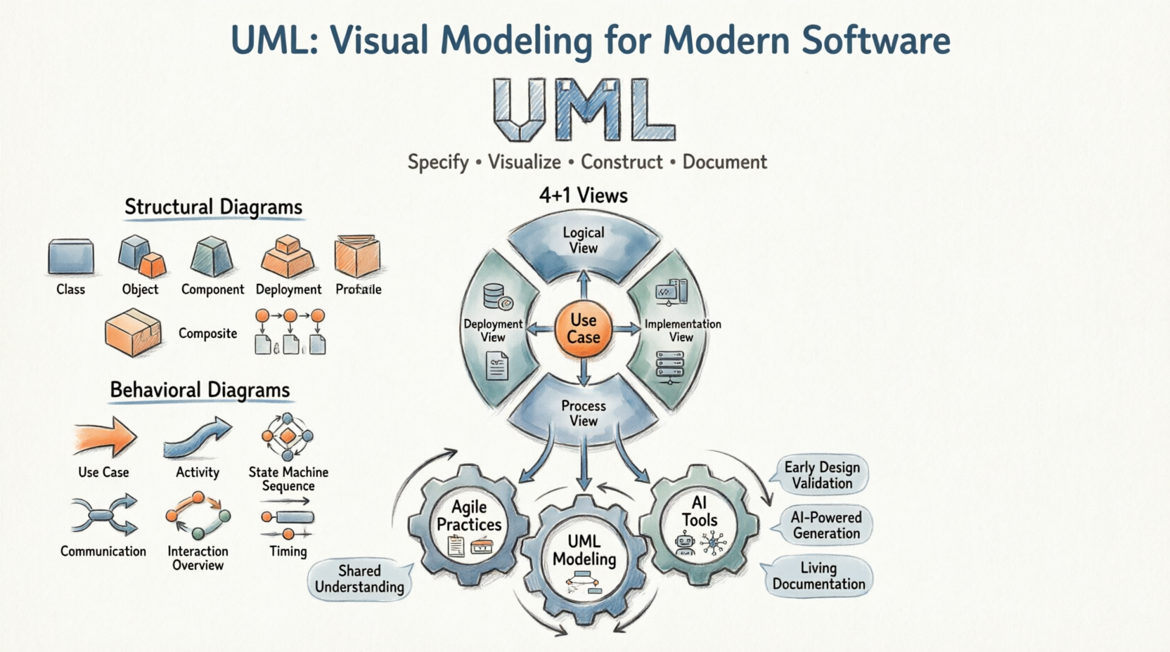
Modeling Architecture Views Using UML: The 4+1 View Model
Real-world systems serve diverse stakeholders: developers, testers, business analysts, end-users, and system architects. To address these varied perspectives, UML supports the 4+1 Views of Software Architecture, a framework that visualizes a system through multiple, interconnected lenses.
The Five Architectural Views
| View | Description | Mandatory? |
|---|---|---|
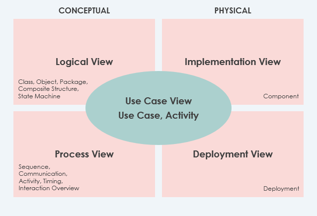
| Use Case View ⭐ | Describes system functionality, external interfaces, and principal users. Contains the Use-Case Model. All other views derive from requirements captured here. | ✅ Yes |
| Logical View | Describes system structure in terms of implementation units: packages, classes, interfaces, and their relationships (dependencies, realizations, compositions). | ✅ Yes |
| Implementation View | Describes how development artifacts are organized in the file system (files, directories, configuration items). Covers both development and deployment artifacts. | ❌ Optional |
| Process View | Describes runtime system structure: processes, threads, EJBs, servlets, DLLs, data stores, and communication connectors. Critical for analyzing performance, reliability, and scalability. | ❌ Optional |
| Deployment View | Describes how software components map to hardware infrastructure (servers, networks, devices). Essential for distributed systems. | ❌ Optional |
Additional View: Data View
-
A specialization of the Logical View
-
Use when persistence is a significant system aspect
-
Helpful when the translation from design model to data model isn’t automated
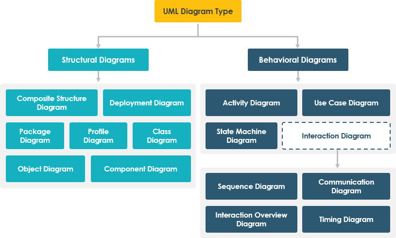
The 14 Types of UML 2 Diagrams
Diagrams are the heart of UML. UML 2.x defines 14 diagram types, broadly categorized into two families:
🏗️ Structural Diagrams (Static)
Show the static structure of the system and its components across different abstraction and implementation levels.
-
Class Diagram
-
Object Diagram
-
Component Diagram
-
Deployment Diagram
-
Package Diagram
-
Composite Structure Diagram
-
Profile Diagram
🔄 Behavioral Diagrams (Dynamic)
Show the dynamic behavior of objects—how the system changes over time through interactions and state transitions.
-
Use Case Diagram
-
Activity Diagram
-
State Machine Diagram
-
Sequence Diagram
-
Communication Diagram
-
Interaction Overview Diagram
-
Timing Diagram
Structural Diagrams in Detail
1. Class Diagrams
Most popular UML diagram in object-oriented development.
Purpose: Describes objects in a system, their attributes, operations, and relationships. Represents the static view of a system.
Key Features:
-
Classes with attributes and methods
-
Relationships: associations, aggregations, compositions, inheritances
-
Multiplicity constraints (e.g.,
0..*) -
Directly mappable to object-oriented programming languages
Use Case: System design, code generation, documentation, reverse engineering
Class Diagram Example
The following Class Diagram represents two classes – User and Attachment. A user can upload multiple attachments, so the two classes are connected with an association, with 0..* as multiplicity on the Attachment side.

2. Object Diagrams
Purpose: Shows a snapshot of the system at a specific moment—an instance of a class diagram.
Key Features:
-
Objects (instances of classes) with actual values
-
Links (instances of associations)
-
Concrete, time-specific representation
Use Case: Validating class designs, illustrating example data structures, debugging
Object Diagram Example
This Object Diagram shows how object instances of User and Attachment classes “look like” at the moment Peter (the user) is trying to upload two attachments. Two Instance Specifications represent the two attachment objects to be uploaded.

3. Component Diagrams
Purpose: Describes the static implementation view—how code is organized into physical components.
Key Features:
-
Components: libraries, files, executables, modules
-
Interfaces and dependencies between components
-
Supports forward/reverse engineering
Use Case: Build management, component reuse, system integration planning
Component Diagram Example

4. Deployment Diagrams
Purpose: Models the physical deployment of software artifacts onto hardware infrastructure.
Key Features:
-
Nodes: hardware devices, execution environments
-
Artifacts: software components deployed on nodes
-
Communication paths between nodes
Use Case: System administration, DevOps planning, infrastructure documentation
Deployment Diagram Example

5. Package Diagrams
Purpose: Organizes model elements into groups (packages) and shows dependencies between them.
Key Features:
-
Packages as namespaces for related elements
-
Dependency, import, and merge relationships
-
Supports multi-layered/multi-tiered architecture modeling
Use Case: Large system organization, modular design, dependency management
Package Diagram Example

6. Composite Structure Diagrams
Purpose: Shows the internal structure of a class or component and how its parts collaborate.
Key Features:
-
Internal parts and their roles
-
Ports for external interaction
-
Connectors defining part-to-part communication
Use Case: Detailed component design, pattern implementation, micro-architecture modeling
Composite Structure Diagram Example

7. Profile Diagrams
Purpose: Extends UML with domain-specific or platform-specific stereotypes and tagged values.
Key Features:
-
Stereotypes: custom model elements
-
Tagged values: additional metadata
-
Constraints: rules for stereotype usage
Use Case: Domain-specific modeling (e.g., healthcare, finance), platform adaptation (e.g., UML for EJB, UML for SOA)
Profile Diagram Example

Behavioral Diagrams in Detail
8. Use Case Diagrams
Purpose: Captures system functionality from an external viewpoint—what the system does for its users.
Key Features:
-
Actors: users or external systems interacting with the system
-
Use cases: units of functionality
-
Relationships: include, extend, generalization
Use Case: Requirements elicitation, stakeholder communication, high-level design
Use Case Diagram Example

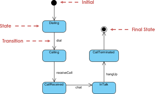
9. State Machine Diagrams
Purpose: Models the lifecycle of an object—how its state changes in response to events.
Key Features:
-
States: conditions during an object’s life
-
Transitions: event-triggered state changes
-
Actions: activities performed during transitions or in states
Use Case: Reactive systems, workflow modeling, protocol design
State Machine Diagram Example
10. Activity Diagrams
Purpose: Models workflows and business processes as a flow of activities.
Key Features:
-
Actions and control flows
-
Decision nodes, forks, joins for branching and concurrency
-
Object flows for data movement
Use Case: Business process modeling, algorithm design, use case elaboration
Activity Diagram Example

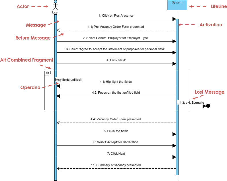
11. Sequence Diagrams
Purpose: Shows object interactions arranged in time sequence—how operations are carried out.
Key Features:
-
Lifelines: participating objects/actors
-
Messages: synchronous, asynchronous, return
-
Activation bars: execution occurrences
-
Combined fragments: loops, alternatives, options
Use Case: Detailed design, API specification, debugging complex interactions
Sequence Diagram Example
12. Communication Diagrams
Purpose: Emphasizes object collaboration and link structure over time ordering.
Key Features:
-
Objects and links (structural focus)
-
Numbered messages showing sequence
-
Equivalent semantics to sequence diagrams
Use Case: Understanding object relationships, refactoring, architectural reviews
Communication Diagram Example

Note: The original image reference appears to link to an activity diagram; in practice, communication diagrams show objects connected by links with numbered messages.
13. Interaction Overview Diagrams
Purpose: Provides a high-level overview of control flow between interactions.
Key Features:
-
Activity diagram structure with interaction nodes
-
References to detailed sequence/communication diagrams
-
Navigation between abstraction levels
Use Case: Complex scenario modeling, system orchestration, documentation navigation
Interaction Overview Diagram Example

14. Timing Diagrams
Purpose: Focuses on timing constraints and state changes over precise time intervals.
Key Features:
-
Time axis progressing left-to-right
-
Lifelines in vertical compartments
-
State timelines and duration constraints
Use Case: Real-time systems, performance analysis, protocol timing verification
Timing Diagram Example

UML in the Age of Agile and AI: Still Relevant?
✅ UML and Agile: Complementary, Not Contradictory
A common misconception is that UML conflicts with Agile principles. In reality, UML enhances Agile practices when applied pragmatically:
| Agile Practice | UML Support |
|---|---|
| User Stories | Use Case Diagrams visualize scope and actor interactions |
| Sprint Planning | Activity & Sequence Diagrams clarify task dependencies |
| Refactoring | Class & Component Diagrams document structural changes |
| Continuous Integration | Deployment Diagrams map environments and pipelines |
| Stakeholder Communication | Visual models bridge technical and non-technical audiences |
Best Practice: Use just enough UML—create lightweight, living diagrams that evolve with the code, not heavyweight documentation that becomes obsolete.
✅ UML and AI: A Powerful Synergy
Generative AI is transforming how we create and consume UML models:
🤖 AI-Enhanced UML Workflows
-
Natural Language to Diagram: Describe a system in plain English; AI generates compliant UML diagrams.
-
Diagram-to-Code Generation: Export diagrams to skeleton code in Java, C#, Python, etc.
-
Intelligent Validation: AI checks diagrams for consistency, completeness, and best practices.
-
Automated Documentation: Generate narrative documentation from diagram metadata.
Real-World AI Tools for UML
-
AI Diagram Chatbot: Draft diagrams through conversational prompts
-
AI WebApps: Guided workflows to evolve architecture from sketch to implementation
-
AI Diagram Generator: Create OMG-compliant UML directly in desktop tools
-
OpenDocs: Embed live, AI-generated diagrams in knowledge bases
Key Insight: AI doesn’t replace UML—it amplifies its value by reducing manual effort and accelerating the design-feedback loop.
Putting UML into Practice with Generative AI
Applying UML principles in real-world software architecture can be challenging. Visual Paradigm’s AI-powered tools bridge the gap between abstract requirements and professional-grade diagrams, helping you visualize complex systems in a fraction of the time.
🚀 AI-Powered UML Tooling
💬 AI Diagram Chatbot
Instant diagram drafting through natural conversation. Perfect for quickly capturing use case views and system behaviors.
🌐 AI WebApps
Step-by-step AI-guided workflows to create and evolve your architecture from simple sketches to detailed implementation views.
⚡ AI Diagram Generator
Generate professional UML diagrams directly within the Visual Paradigm Desktop, ensuring full compliance with OMG standards.
📝 OpenDocs
A modern knowledge management system to centralize your documents and embed live AI-generated diagrams.
Ready to modernize your modeling process?
Explore the AI Diagramming Ecosystem →
Summary: Why UML Endures
-
Open Standard: UML is non-proprietary, maintained by OMG, and accessible to all.
-
Community Adoption: Supported by methodologists, organizations, and tool vendors worldwide.
-
Methodological Synthesis: Builds upon semantics from Booch, OMT, OOSE, and other leading methods.
-
Dual Unification:
-
Harmonizes previously fragmented modeling notations
-
Unifies perspectives across system types (business/software), development phases (analysis/design/implementation), and conceptual levels
-
UML’s Enduring Value Proposition
| Challenge | UML Solution |
|---|---|
| Complexity | Visual abstraction reduces cognitive load |
| Communication | Shared visual language aligns stakeholders |
| Documentation | Living diagrams stay synchronized with code |
| Quality | Early modeling catches design flaws pre-implementation |
| Adaptability | Diagrams evolve with the system through iterations |
Final Thought: UML is not about creating perfect diagrams—it’s about creating shared understanding. In an era of rapid change, that understanding is more valuable than ever.
References
-
What is UML? A Comprehensive Guide to Unified Modeling Language: This in-depth introduction explains the fundamental concepts of UML and its critical role in software design and system modeling.
-
Overview of the 14 UML Diagram Types – Visual Paradigm: This resource explores the 14 distinct UML diagram types, each serving specific modeling purposes with standardized notation.
-
Practical Guide to UML: From Theory to Real-World Application: A hands-on tutorial that demonstrates how to apply use case, class, sequence, and activity diagrams to real software projects.
-
Adopting UML in Agile Projects: A Complete Tutorial with Visual Paradigm: This article provides guidance on integrating UML modeling into Agile workflows to improve planning, communication, and project clarity.
-
AI-Powered UML Class Diagram Generator by Visual Paradigm: This tool utilizes a Generative AI engine to transform natural language descriptions into accurate UML class diagrams automatically.
-
Visual Paradigm – AI-Powered UML Sequence Diagrams: This resource teaches users how to generate professional UML sequence diagrams instantly from simple text prompts using advanced AI modeling.
-
What Is a Use Case Diagram? – A Complete Guide to UML Modeling: An in-depth explanation of use case components and best practices for requirements modeling and system design.
-
What is a Package Diagram in UML? – Visual Paradigm Guide: This guide focuses on organizing and managing complex systems through the logical grouping of elements using package diagrams.
-
What is a Deployment Diagram? A Complete Guide to UML Deployment Diagrams: This comprehensive guide explains how to model the physical architecture of a software system, including hardware and software mapping.
-
UML Diagrams Explained: A Beginner’s Guide: A clear, foundational resource that introduces the key types of UML diagrams and their practical applications in the software development lifecycle.