Software architecture is often a challenge of communication. Teams struggle to align on how systems work, how data flows, and where boundaries lie. Without a standardized approach, diagrams become cluttered, confusing, or overly specific. The C4 Model provides a structured hierarchy for creating software architecture diagrams. It allows teams to visualize system structure at different levels of detail.
This guide explores the four levels of the C4 Model. We will examine when to use each level, who the intended audience is, and how to maintain clarity across your technical documentation. By following this framework, teams can ensure that architectural knowledge remains accessible and accurate.
📊 The C4 Model Overview
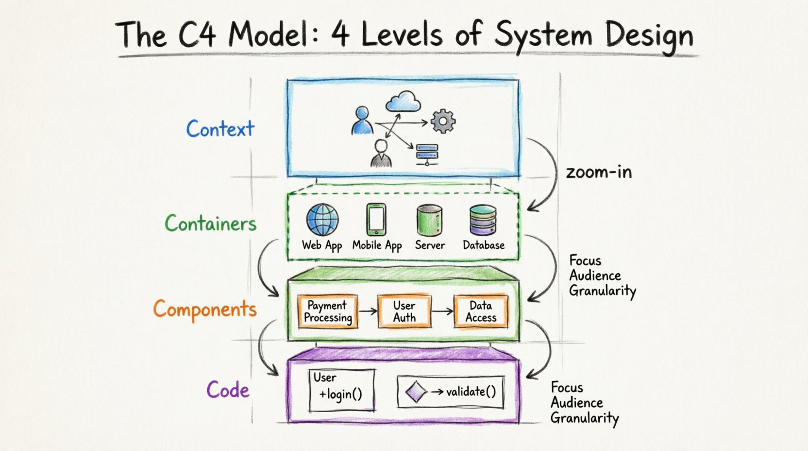
The C4 Model stands for Context, Containers, Components, and Code. It is a hierarchy that moves from the big picture down to the specific implementation. Each level answers different questions for different stakeholders. The model is technology-agnostic, meaning it focuses on structure and responsibility rather than specific programming languages or platforms.
Using a single diagram to explain everything often leads to cognitive overload. The C4 Model solves this by encouraging the use of multiple diagrams for the same system, each zoomed in at a different depth.
Below is a summary of the four levels:
| Level | Name | Focus | Typical Audience | Granularity |
|---|---|---|---|---|
| 1 | Context | System boundaries | Stakeholders, Managers | Low |
| 2 | Containers | Technology choices | Developers, Architects | Medium |
| 3 | Components | Internal logic | Developers | High |
| 4 | Code | Implementation details | Developers, Code Reviewers | Very High |
🌍 Level 1: System in Context
The first level provides the big picture. It answers the question: “How does this system fit into the wider world?” This diagram is usually the starting point for any architectural discussion.
🎯 Purpose and Audience
The primary goal of a Level 1 diagram is to establish the scope. It is designed for a broad audience, including product managers, business stakeholders, and new team members. These individuals need to understand the value proposition and external dependencies without getting bogged down in technical details.
📝 What to Include
A Context diagram should contain the following elements:
- The System Itself: Represented as a central box. This is the software or service being documented.
- People: Users or actors who interact with the system. This includes administrators, end-users, or external clients.
- Other Systems: External services that the system communicates with. Examples include payment gateways, email services, or legacy databases.
- Relationships: Lines connecting the system to people or other systems. These lines represent data flow or interaction.
🚫 What to Avoid
Do not include internal details at this stage. Avoid showing specific servers, database tables, or API endpoints. Keeping the view abstract ensures that the diagram remains valid even if internal technologies change.
📦 Level 2: Containers
Once the boundaries are set, the second level zooms in to reveal what constitutes the system. A container is a high-level building block. It represents a distinct runtime environment.
🎯 Purpose and Audience
Level 2 diagrams are primarily for developers and architects. They need to know how the system is deployed and what technologies are in play. This level bridges the gap between business requirements and technical implementation.
📝 What to Include
A Container diagram breaks the system box from Level 1 into its constituent parts. Common elements include:
- Web Applications: Browser-based interfaces or Single Page Applications (SPAs).
- Mobile Applications: Native apps for iOS or Android.
- Server-Side Applications: Backend services running on servers or cloud platforms.
- Databases: Persistent storage systems, whether SQL or NoSQL.
- Cloud Services: Managed services provided by third parties, such as object storage or message queues.
Connections between containers should show how they communicate. This might involve protocols like HTTP, TCP/IP, or database queries.
🚫 What to Avoid
Avoid showing specific microservices unless they are distinct containers. Do not list every function or class within a container. If a container contains many services, it is better to split them into separate diagrams rather than cluttering the view.
⚙️ Level 3: Components
Level 3 focuses on the internal structure of a single container. It breaks down the container into smaller, manageable pieces called components.
🎯 Purpose and Audience
This level is for developers working within the system. It helps them understand where specific functionality lives and how different parts of the codebase interact. It is essential for onboarding new engineers and planning feature work.
📝 What to Include
Components are logical groupings of functionality. They can represent:
- Software Libraries: Reusable code blocks.
- Modules: Distinct sections of the application logic.
- Classes: Specific object-oriented structures.
- Functions: Standalone procedures or methods.
The key is to group components by responsibility. A component should have a clear purpose. For example, a “Payment Processing” component might contain logic for validating credit cards and communicating with a gateway.
🚫 What to Avoid
Do not draw every single class in the system. This leads to diagrams that are impossible to read. Focus on the major architectural decisions and critical paths. If a component is too complex, it may warrant its own sub-diagram.
💻 Level 4: Code
The fourth level is the most granular. It deals with the actual code structure. However, this level is often optional. Many teams find that Level 3 is sufficient for most architectural documentation.
🎯 Purpose and Audience
Code diagrams are for developers who need to understand specific implementation details. They are useful for complex algorithms, critical security flows, or performance-critical sections.
📝 What to Include
At this level, you might visualize:
- Sequence Diagrams: Showing the order of operations between objects.
- Class Diagrams: Showing the inheritance and relationships between classes.
- Data Structures: Specific data models used in memory.
This level often overlaps with standard software engineering documentation. The C4 Model suggests using it sparingly to avoid maintenance overhead.
🚫 What to Avoid
Do not include variable names or specific method signatures unless they are critical to the architecture. If you need to document specific code logic, a code comment or a dedicated technical wiki page is often better than a diagram.
🛠️ Best Practices for Diagram Maintenance
Creating diagrams is only half the work. Keeping them accurate over time is crucial. Outdated diagrams can mislead teams and cause technical debt.
🔄 Integration with Workflow
Integrate diagram updates into your development process. Treat architecture documentation as code. When a pull request changes the system structure, it should also update the relevant diagram. This ensures the documentation evolves alongside the software.
👥 Collaborative Ownership
Assign ownership of diagrams to specific team members. A single person cannot maintain all architecture documentation in a growing team. Designate owners for each container or component level.
🎨 Visual Consistency
Use a consistent style guide. Define colors for different types of elements (e.g., blue for people, green for databases). This helps readers scan diagrams quickly and understand the layout without reading every label.
📉 Common Pitfalls to Avoid
Even with a good model, teams can make mistakes. Being aware of common errors helps maintain the quality of your documentation.
❌ Mixing Levels
One of the most frequent issues is mixing levels in a single diagram. Do not show code classes inside a Context diagram. Keep the abstraction levels separate. If a diagram looks confusing, check if you have zoomed in too far or too little.
❌ Over-Engineering
Not every system needs a Level 4 diagram. If the system is simple, Level 2 might be enough. Do not force the model where it does not add value. Start small and add detail only when necessary.
❌ Ignoring Relationships
Focus on boxes and lines, but forget the meaning of the connections. Ensure every line has a label describing the data or protocol being exchanged. Unlabeled arrows are useless for understanding system behavior.
📈 Benefits of the C4 Model
Adopting this structured approach brings several advantages to a technical team.
- Shared Understanding: Everyone speaks the same language regarding system boundaries and responsibilities.
- Faster Onboarding: New hires can understand the system structure quickly by starting at Level 1 and drilling down.
- Reduced Complexity: Breaking a system into layers makes it easier to reason about.
- Flexibility: The model works for monolithic applications, microservices, or anything in between.
🔍 When to Stop Documenting
There is a point of diminishing returns. If you spend more time updating a diagram than writing code, you are likely over-documenting. Use your judgment.
Ask yourself:
- Does this diagram help me understand the system?
- Will this diagram help someone else understand the system?
- Is the cost of updating this diagram too high?
If the answer to the last question is yes, simplify the diagram or remove it. The goal is clarity, not completeness.
🚀 Summary
The C4 Model offers a practical way to manage software architecture documentation. By separating concerns into Context, Containers, Components, and Code, teams can communicate effectively at every level of the stack. It encourages a layered approach that prevents diagrams from becoming overwhelming.
Start with the big picture. Define the boundaries. Then, zoom in only as deep as the audience requires. Maintain the diagrams alongside the code. This disciplined approach leads to better software design and smoother collaboration.