System analysis relies heavily on visual communication to bridge the gap between technical requirements and functional design. Among the various modeling techniques available, the Data Flow Diagram (DFD) stands out as a fundamental tool for mapping how information moves through a system. This guide provides a comprehensive overview of DFDs, breaking down their components, structures, and applications without relying on specific software products. Whether you are a student, a business analyst, or a developer, understanding these diagrams is essential for clarity and precision.
🧩 What Is a Data Flow Diagram?
A Data Flow Diagram is a graphical representation of the flow of data through an information system. Unlike program flowcharts that focus on control logic or decision points, a DFD focuses strictly on data. It illustrates how data enters the system, how it is processed, where it is stored, and where it exits. This distinction is critical because it separates the what of a system from the how.
Think of a DFD as a map for data traffic. It does not show the specific code or hardware used, but rather the logical pathways that information follows. This abstraction allows stakeholders to understand the system at a high level before diving into technical implementation details.
- Focus: Data movement and transformation.
- Scope: Logical processes rather than physical implementation.
- Users: Business analysts, system designers, and project managers.
- Output: A clear visualization of system boundaries and interactions.
🛠️ Core Components of a DFD
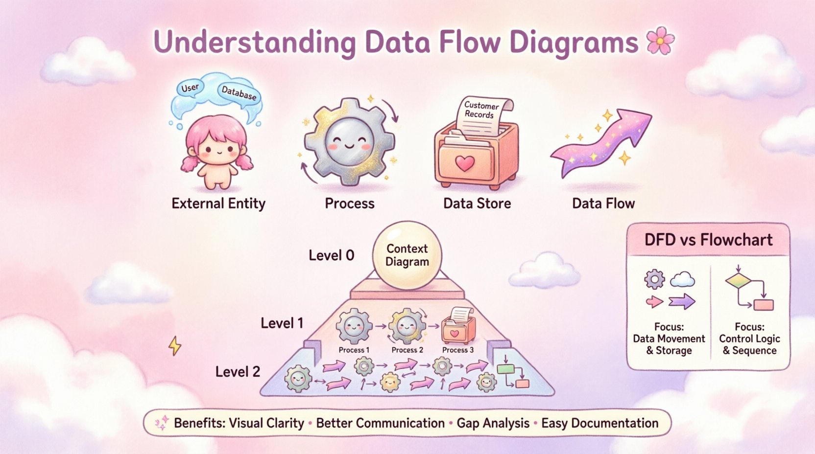
To construct a valid Data Flow Diagram, you must understand the four fundamental shapes that make up the diagram. Each shape represents a specific function or entity within the system. Understanding these components is the first step in creating accurate models.
1. External Entities (👤)
External entities are sources or destinations of data that lie outside the boundary of the system being modeled. They interact with the system but are not part of it. These can be people, organizations, or other systems.
- Terminology: Also known as terminators, sources, sinks, or actors.
- Example: A customer placing an order, a bank processing a payment, or an external weather service.
- Role: Initiates data input or receives data output.
2. Processes (⚙️)
Processes are actions that transform input data into output data. They change the form, content, or distribution of the data. Every process must have at least one input and at least one output to be valid.
- Terminology: Functions, transformations, or activities.
- Example: Calculating tax, validating a user login, or generating an invoice.
- Rule: A process cannot exist without data flowing into it or out of it.
3. Data Stores (🗃️)
Data stores represent where information is held within the system. This is not a physical database server, but rather a logical repository. It indicates that data is being saved for later retrieval or use.
- Terminology: Files, databases, or repositories.
- Example: A customer database, a log of transactions, or a temporary cache.
- Interaction: Data flows in to be stored and flows out to be retrieved.
4. Data Flows (➡️)
Data flows show the movement of data between entities, processes, and stores. They are represented by arrows. The direction of the arrow indicates the path the data takes. The label on the arrow describes the content of the data.
- Terminology: Connections, links, or streams.
- Requirement: Must be labeled with a noun phrase (e.g., “Order Details”).
- Rule: Arrows cannot cross data stores directly without a process in between.
📊 Comparing Notation Styles
There are two primary styles for drawing Data Flow Diagrams. While they represent the same concepts, the symbols used differ slightly. Knowing the difference helps in interpreting diagrams created by different teams or methodologies.
| Feature | Yourdon & DeMarco | Gane & Sarson |
|---|---|---|
| Processes | Rounded Rectangles | Rectangles with rounded corners |
| External Entities | Rectangles | Squares |
| Data Stores | Open-ended Rectangle | Open Rectangle |
| Data Flows | Arrow | Arrow |
| Labeling | Numbers on Process Circles | Numbers on Process Rectangles |
Both styles are valid, but consistency within a project is paramount. Choose one style and adhere to it throughout the documentation.
📉 Levels of Decomposition
Data Flow Diagrams are often created in layers, a technique known as decomposition. This allows you to start with a high-level overview and gradually add detail. Breaking a complex system into manageable chunks makes the diagram easier to read and maintain.
Level 0: The Context Diagram
The Context Diagram is the highest level of abstraction. It shows the system as a single process and its relationship with external entities. It answers the question: “What is the system boundary?”
- Scope: One central process representing the entire system.
- Detail: No internal data stores or sub-processes shown.
- Usage: Used to define the scope for stakeholders and management.
Level 1: The Decomposition
Level 1 breaks the single process from the Context Diagram into major sub-processes. This reveals the primary functions of the system. It is the most common level of detail used for system design.
- Detail: Shows main processes, major data stores, and external entities.
- Usage: Used by developers to understand major functional areas.
Level 2 and Beyond
Further decomposition (Level 2, Level 3) drills down into specific sub-processes. This is necessary only for complex functions that require detailed specification.
- Detail: Granular steps within a Level 1 process.
- Usage: Used for detailed logic specification or documentation.
It is important to maintain consistency between levels. The inputs and outputs of a Level 1 process must match the inputs and outputs of the single process in the Level 0 diagram. This is known as balancing.
🛣️ How to Create a Data Flow Diagram
Creating a DFD is a systematic process. Following a structured approach ensures that the resulting diagram is accurate and useful. You do not need specialized tools to begin; you can start with pen and paper to explore the logic.
Step 1: Identify External Entities
Start by determining who or what interacts with the system. List all users, departments, or external systems that send data to the system or receive data from it.
- Question: Who initiates the process?
- Question: Who receives the final result?
Step 2: Define the Main Process
Represent the entire system as a single bubble or rectangle. This is your Level 0 diagram. Draw arrows connecting the external entities to this central process to show the major data inputs and outputs.
Step 3: Decompose the Main Process
Break the central process down into sub-processes. Identify the major functions that need to happen to transform input into output. Label these clearly.
Step 4: Add Data Stores
Identify where data needs to be saved. If a piece of information is needed later or verified against history, it belongs in a data store. Connect processes to these stores.
Step 5: Label Data Flows
Ensure every arrow has a label. The label should describe the data, not the action. For example, use “Invoice Data” instead of “Send Invoice”.
Step 6: Review for Balancing
Check that the inputs and outputs of the parent process match the sum of the inputs and outputs of the child processes. If a data flow disappears or appears without a source, the diagram is unbalanced.
🚫 Common Mistakes to Avoid
Even experienced analysts can make errors when modeling systems. Being aware of common pitfalls helps you produce cleaner, more accurate diagrams.
- Black Holes: A process with only inputs and no outputs. Data enters but never leaves, which implies a system error.
- Miracles: A process with only outputs and no inputs. Data appears out of nowhere, which is logically impossible.
- Data Store Errors: Connecting a data store directly to an external entity without a process in between. Data cannot move directly from storage to an outside source.
- Overlapping Labels: Using verbs for data flow labels instead of nouns. Data flows are nouns (e.g., “Report”), not actions (e.g., “Generate Report”).
- Crossing Lines: While sometimes unavoidable, crossing lines can make the diagram difficult to read. Try to route flows neatly.
🆚 DFD vs. Flowcharts
It is common to confuse Data Flow Diagrams with Flowcharts. While both use shapes and arrows, they serve different purposes. Understanding the distinction prevents confusion during system design.
| Aspect | Data Flow Diagram (DFD) | Flowchart |
|---|---|---|
| Focus | Data movement and transformation | Control flow and decision logic |
| Process Shape | Circle or Rounded Rectangle | Rectangle |
| Decisions | Not represented | Represented by Diamonds |
| Looping | Not explicitly shown | Explicitly shown with arrows |
| Time | Time-independent | Time-dependent |
If you need to describe the sequence of steps, including decisions and loops, a flowchart is appropriate. If you need to describe the data requirements and storage, a DFD is the correct choice.
🌟 Benefits of Using Data Flow Diagrams
Why invest time in creating these diagrams? The value lies in clarity and communication. A well-drawn DFD serves as a single source of truth for the system’s data requirements.
- Visual Clarity: Complex systems become easier to understand when visualized.
- Communication: Bridges the gap between technical teams and business stakeholders.
- Gap Analysis: Helps identify missing data flows or undefined processes.
- Documentation: Provides a baseline for future system maintenance and upgrades.
- Testing: Helps testers understand what data should be expected at each stage.
🔍 Real-World Application Example
Consider a simple library management system. How would a DFD look for this scenario?
- External Entity: The Librarian and The Member.
- Process: Issue Book, Return Book, Search Catalog.
- Data Store: Book Inventory, Member Records.
- Flow: A Member requests a book (Input). The system checks inventory (Process). If available, it updates the record (Process). The book is issued (Output).
This example shows how data moves from the member to the system, interacts with the library records, and results in a transaction. No specific software is mentioned; the logic stands on its own.
📝 Summary of Best Practices
To ensure your Data Flow Diagrams are effective, keep these guidelines in mind during the creation process.
- Keep it Simple: Avoid overcrowding a single diagram. Use decomposition.
- Use Consistent Naming: Ensure data flow labels match across all levels.
- Validate with Stakeholders: Review the diagrams with the people who use the system.
- Focus on Data: Remember that this is about data, not control or timing.
- Iterate: Diagrams are rarely perfect on the first draft. Expect to revise them.
By adhering to these principles, you create models that are robust, clear, and valuable assets for any project. The effort put into mapping the data flow pays dividends in reduced errors and clearer requirements.