In modern software architecture, the shift from monolithic structures to distributed systems is a common trajectory. Organizations often begin with a unified codebase and a centralized database schema. Over time, this structure creates bottlenecks. The Entity Relationship Diagram (ERD) that once served as a clear blueprint for the application becomes a complex web of interdependencies. Transforming this monolithic ERD into a foundation for a modular service mesh requires careful planning, technical discipline, and a clear understanding of data boundaries. This guide explores the practical steps, challenges, and architectural decisions involved in this transformation.
Architecture is not merely about moving code; it is about moving data ownership. When an ERD is monolithic, tables often reference each other across functional domains. A single query might traverse five different tables representing different business units. This tight coupling makes independent deployment impossible. By decomposing this diagram and aligning it with a service mesh, teams can achieve isolation and scalability. The following sections detail the methodology used to achieve this transition without relying on specific vendor tools.
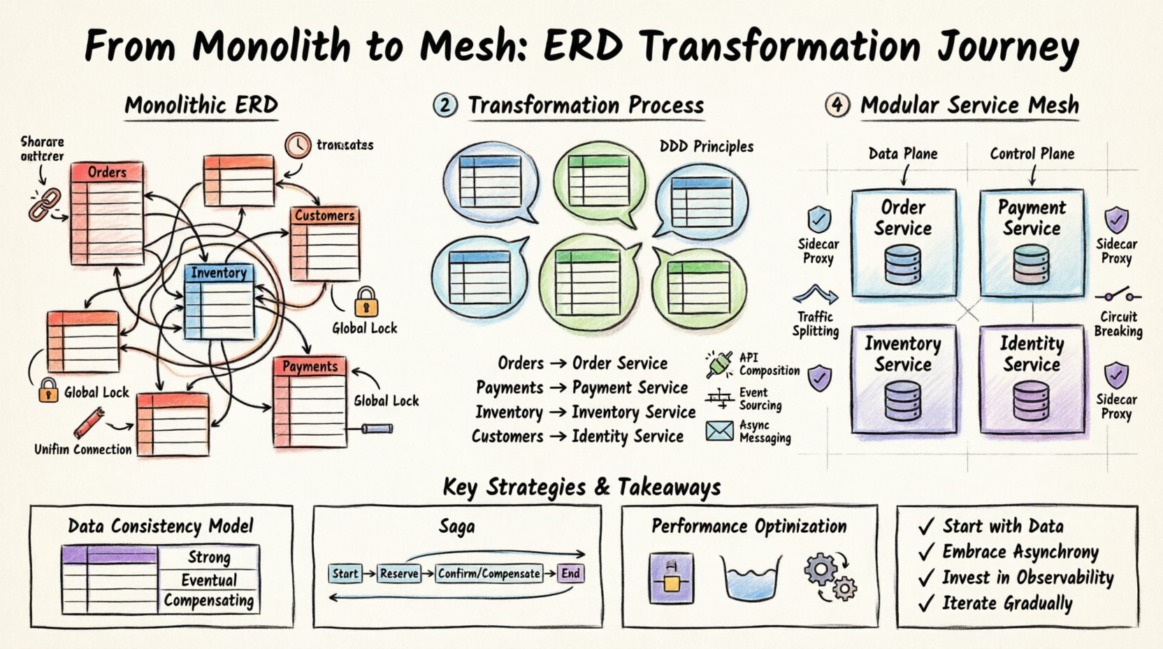
🏗️ Understanding the Starting Point: The Monolithic ERD
Before any changes are made, the current state must be fully understood. A monolithic ERD typically exhibits characteristics that signal high coupling. These characteristics include:
- Shared Foreign Keys: Tables in different modules reference the same unique identifiers, creating direct dependencies.
- Large Transaction Blocks: Database transactions span multiple tables that logically belong to different business contexts.
- Global Schema Locks: Schema changes require downtime or complex migration scripts affecting the entire application.
- Unified Connection Pools: The application shares a single pool of database connections, limiting concurrency for specific high-traffic features.
Visualizing this structure often reveals a “spaghetti” pattern in the diagram. Lines connect tables across the entire layout, suggesting that no single component is self-contained. In a service-oriented approach, these connections must be severed or abstracted. The goal is to identify where data lives and who should own it.
🧩 Defining Bounded Contexts
The core of the transformation lies in Domain-Driven Design (DDD) principles. You must identify bounded contexts within the monolithic ERD. A bounded context is a specific boundary within which a particular domain model applies. In the context of an ERD, this means grouping tables that logically belong together.
To achieve this, perform a data lineage analysis. Trace how data flows from creation to consumption. Ask the following questions:
- Which tables are updated by the same business process?
- Which tables are read frequently by specific user roles?
- Which relationships represent a “has-a” or “belongs-to” relationship that crosses functional lines?
Once these groups are identified, assign them to specific service boundaries. This process is not always one-to-one. Multiple tables may belong to a single service, while a single table might be split across services if the data usage patterns differ significantly.
Example: Decomposition Strategy
Consider a scenario where the ERD contains a massive Orders table linked to Customers, Inventory, and Payments. In a monolith, this is one table. In a modular system, these become distinct entities.
| Monolithic Entity | Proposed Service Boundary | Reasoning |
|---|---|---|
Orders (Main) |
Order Service | Primary business logic resides here. |
Payments |
Payment Service | Requires different security and compliance standards. |
Inventory |
Inventory Service | Requires high availability and different locking strategies. |
Customers |
Identity Service | Shared across multiple domains, needs centralization. |
🔄 Restructuring Data Relationships
Once services are defined, the relationships in the ERD must change. In a monolith, a foreign key constraint enforces data integrity. In a distributed system, enforcing foreign keys across network boundaries is inefficient and prone to failure. Instead, relationships are managed through application logic and messaging.
This shift requires adopting specific patterns to maintain consistency:
- API Composition: Services expose APIs that return summarized data, hiding internal database structures.
- Event Sourcing: State changes are recorded as a sequence of events. Services subscribe to these events to update their local state.
- Async Messaging: Instead of direct calls, services communicate via a message broker to handle load spikes and failures.
The ERD evolves from a single diagram into a collection of service schemas. Each service has its own data model, optimized for its specific read and write patterns. This reduces the complexity of any single query.
🛡️ Implementing the Service Mesh Layer
With services defined and data boundaries established, the next layer is the service mesh. This infrastructure layer handles service-to-service communication. It sits between the application code and the network, providing visibility and control.
Key Components of the Mesh
While specific tools vary, the architectural components remain consistent. The mesh typically consists of:
- Data Plane: Lightweight proxies that intercept traffic between services.
- Control Plane: A central management component that configures the proxies.
- Sidecar Pattern: Each service instance runs alongside a proxy container.
The service mesh allows for policies that were previously difficult to implement in a monolith. For example, you can enforce rate limits on specific services without changing the application code. You can also implement mutual TLS encryption between services automatically.
Traffic Management
One of the primary benefits of the mesh is traffic splitting. During deployment, you can route a percentage of traffic to a new version of a service. This allows for testing in a production environment without risking the entire system. The mesh handles the routing rules based on headers, paths, or weight.
Additionally, circuit breaking is critical. If a downstream service becomes unresponsive, the mesh can stop sending traffic to it, preventing a cascade failure. This protects the integrity of the system when individual components fail.
📊 Data Consistency and Governance
Splitting the ERD introduces the challenge of distributed transactions. In a monolith, ACID properties are managed by the database. In a distributed system, maintaining these properties across multiple databases is complex. You must choose a strategy that fits the business requirements.
Consistency Models
Different services may have different consistency needs. The following table outlines common strategies:
| Strategy | Use Case | Trade-off |
|---|---|---|
| Strong Consistency | Financial ledgers | Higher latency, lower availability. |
| Eventual Consistency | Inventory counts | Lower latency, temporary data mismatch. |
| Compensating Transactions | Order cancellation | Complex logic, requires rollback mechanisms. |
The Saga pattern is a common approach for managing long-running transactions. It breaks a transaction into a series of local transactions. If one fails, compensating actions are triggered to undo the previous steps. This ensures that the system remains in a valid state even if parts of the process fail.
Schema Evolution
With separate databases, schema changes are easier to manage. A team can modify the schema for their service without coordinating with other teams. However, backward compatibility is still necessary. APIs must handle versioning gracefully. Old clients should continue to work while new clients adopt the new schema.
🚀 Performance and Scalability Considerations
Transforming the architecture impacts performance. Network latency is introduced when services call each other. To mitigate this, the following optimizations are recommended:
- Caching: Frequently accessed data should be cached at the edge or within the service. This reduces database load and network hops.
- Connection Pooling: Each service should maintain its own connection pool to the database. This prevents contention.
- Asynchronous Processing: Non-critical tasks, such as sending emails or generating reports, should be processed asynchronously.
Monitoring is essential. You need visibility into the latency between services. Distributed tracing allows you to follow a request as it flows through the mesh. This helps identify bottlenecks that were previously hidden in a monolithic log.
🔍 Challenges and Mitigation
While the benefits are clear, the transition is not without risks. Teams often encounter specific hurdles during the migration.
1. Increased Complexity
Debugging a distributed system is harder than debugging a monolith. You need to understand the network topology, the service dependencies, and the data flow. Mitigation involves investing in robust observability tools and training.
2. Data Duplication
To avoid network calls for every read, services may duplicate data. This leads to storage overhead and the need for synchronization. Mitigation involves careful design of read models and using materialized views where appropriate.
3. Operational Overhead
Managing many services requires more infrastructure. You need to handle deployment, scaling, and health checks for each component. Automation is key here. Infrastructure as Code ensures that the environment is reproducible.
🛠️ Operational Summary
The journey from a monolithic ERD to a modular service mesh is a significant architectural shift. It requires more than just code refactoring; it demands a change in how data and communication are managed. By defining clear boundaries, adopting event-driven patterns, and leveraging a service mesh for traffic control, organizations can achieve greater agility and resilience.
Key takeaways for this transformation include:
- Start with Data: Understand the ERD before writing code. Data ownership drives service boundaries.
- Embrace Asynchrony: Use messaging to decouple services and improve resilience.
- Invest in Observability: You cannot manage what you cannot see. Implement tracing and logging early.
- Iterate Gradually: Do not attempt a “big bang” migration. Move functionality incrementally.
This approach ensures that the system remains maintainable as it grows. The resulting architecture supports independent scaling and faster deployment cycles. While the initial effort is substantial, the long-term value of modularity and isolation justifies the investment. The ERD is no longer a constraint; it becomes a map for a scalable, resilient distributed system.