In complex software ecosystems, the most significant friction often arises not from code syntax or infrastructure latency, but from uncertainty regarding who owns what. When a production incident occurs, teams frequently spend valuable time determining responsibility rather than resolving the issue. This ambiguity creates technical debt, slows delivery, and erodes trust between development groups. To mitigate this, architects and engineering leaders must move beyond high-level diagrams and adopt structured approaches that define boundaries with precision.
Integrating the C4 Model with Domain-Driven Design (DDD) Context Maps offers a robust framework for clarifying system ownership. This approach visualizes the boundaries between systems and explicitly defines the relationships that govern interaction. By establishing clear context maps, organizations can reduce ambiguity, streamline communication, and ensure accountability without stifling collaboration.
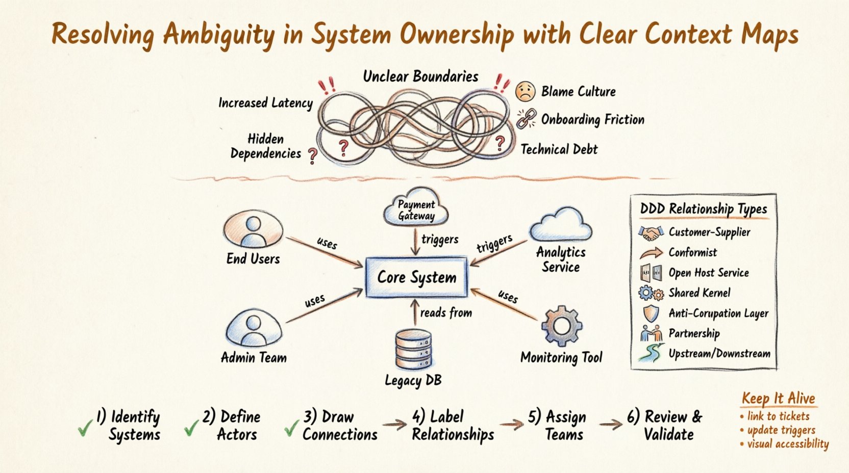
🔴 The Cost of Unclear Boundaries
When system ownership is vague, the consequences ripple through the entire engineering lifecycle. Teams operate in silos or, conversely, overstep boundaries, leading to fragile architectures. The following points outline the tangible impacts of ambiguity:
- Increased Latency: Decisions regarding changes require cross-team consensus, often involving meetings that delay deployment cycles.
- Hidden Dependencies: Without a map, teams unknowingly rely on undocumented interfaces, causing breakage when updates occur elsewhere.
- Blame Culture: When failures happen, the lack of defined ownership leads to finger-pointing rather than root cause analysis.
- Onboarding Friction: New engineers struggle to understand the system landscape, requiring more mentorship time and slowing productivity.
- Technical Debt Accumulation: Without clear ownership, no single team feels responsible for refactoring legacy components, leading to decay.
Ambiguity thrives where documentation is static or non-existent. Dynamic, visual representations of ownership help teams maintain a shared mental model of the architecture.
🏗️ C4 Model: A Foundation for Clarity
The C4 Model provides a standardized way to document software architecture. It uses four levels of abstraction to describe systems, moving from the broad context down to code implementation. While the model itself is a documentation standard, its Level 1: Context Diagram is the critical starting point for defining ownership.
Understanding the Context Layer
The Context Diagram (Level 1) depicts the system as a single black box and its interaction with people and other systems. This level is unique because it forces architects to define the perimeter of their responsibility. It answers the fundamental question: “What is inside our boundary, and what is outside?”
By strictly adhering to the C4 structure for this level, teams avoid the common pitfall of over-complicating the overview. The focus remains on the system’s purpose and its external dependencies. This clarity is essential before diving into containers or components.
Why Context Matters for Ownership
Ownership is defined by boundaries. If a diagram shows a system interacting with five external entities, the team must decide which of those interactions are managed by them and which are managed by others. The C4 Model provides the visual vocabulary to make these decisions explicit.
🗺️ Context Maps as Ownership Tools
Context Maps originate from Domain-Driven Design. They are not merely architectural diagrams; they are strategic tools used to map the relationships between different subdomains within a system. When applied to the C4 Context Diagram, they transform a static picture into a dynamic agreement of ownership.
Defining the Relationship
A Context Map does not just show a line between two systems. It labels the relationship. This label dictates the level of coupling and the nature of the ownership contract. For example, a “Customer-Supplier” relationship implies one team provides a service and another consumes it, creating a clear service-owner hierarchy.
Using Context Maps ensures that every connection in a C4 diagram has a defined governance model. This prevents the “spaghetti architecture” syndrome where systems interact freely without agreed-upon protocols.
Visualizing Boundaries
The visual representation of a Context Map highlights where the handoff occurs. It shows where one team’s responsibility ends and another’s begins. This is crucial for microservices architectures where services are often distributed across different organizational units.
- Explicit Connections: Every line represents a dependency that must be managed.
- Implicit Boundaries: Gaps in the map indicate areas where ownership is undefined and require attention.
- Directionality: Arrows indicate the flow of data, helping to identify which team initiates communication and which responds.
🤝 Types of Relationships & Ownership Implications
Not all relationships carry the same weight. Understanding the specific type of connection helps assign the correct level of responsibility. The table below outlines common relationship types and their impact on ownership.
| Relationship Type | Ownership Implication | Communication Style |
|---|---|---|
| Customer-Supplier | The Supplier owns the contract and stability. The Customer owns the consumption logic. | Formal contracts, versioning, strict SLAs. |
| Conformist | The Consumer must adapt to the Supplier. No influence over the upstream system. | Adaptation logic, wrapper patterns, strict adherence. |
| Open Host Service | The Supplier exposes a standard interface. Multiple Consumers can interact without disrupting the core. | Public APIs, documentation, backward compatibility. |
| Shared Kernel | Both teams share code and data. High coupling requires close coordination. | Joint development, shared repositories, frequent syncs. |
| Anti-Corruption Layer | The Consumer builds a barrier to protect its domain from the Supplier’s complexity. | Translation services, isolation, testing boundaries. |
| Partnership | Both teams commit to mutual development. High collaboration required. | Joint roadmaps, shared goals, frequent communication. |
| Upstream/Downstream | Upstream defines the contract; Downstream is responsible for implementation. | Interface definitions, integration testing. |
Adopting these specific labels prevents vague descriptions like “connected to” or “talks with.” It forces the teams to agree on the mechanics of their interaction before writing code.
📝 Step-by-Step: Mapping Your System’s Ownership
Implementing this approach requires a structured process. It is not enough to draw a diagram once and file it away. The process must be integrated into the workflow.
1. Identify the Core Systems
Start by listing the critical systems that make up the architecture. In the C4 Model, these are the Level 1 boxes. Ensure every major business function has a corresponding system box.
2. Define the Actors
Identify the external users and systems that interact with the core. This includes human actors, third-party APIs, and internal services. Clarity here defines the perimeter of the system.
3. Draw the Connections
Connect the systems. Do not guess the relationships. If you are unsure, mark it as “Unknown” and schedule a workshop to resolve it. Guessing leads to incorrect assumptions about ownership.
4. Label the Relationships
Apply the Context Map labels discussed earlier. Assign a specific relationship type to every connection. This step is where ownership is formally assigned.
5. Assign Team Ownership
For each system box, designate a primary team. For each relationship, designate the team responsible for maintaining the contract. This ensures that for every line drawn, someone is accountable.
6. Review and Validate
Conduct a review with all stakeholders. The goal is to confirm that the map reflects reality. If a team feels the map does not match their workflow, adjust it immediately.
⚠️ Avoiding Common Mapping Traps
Even with a structured approach, teams often fall into patterns that undermine the clarity of the map. Awareness of these pitfalls is essential for success.
- Over-Engineering: Trying to map every single API call at the Context level. This creates noise. The Context Diagram should remain high-level.
- Static Documentation: Creating a map and never updating it. If the map is not current, it becomes a source of confusion rather than clarity.
- Ignoring the Human Element: Focusing only on systems and ignoring the teams that operate them. Ownership ultimately resides with people, not servers.
- Ambiguous Labels: Using terms like “Integration” without specifying the nature of that integration. Be precise with relationship types.
- Lack of Governance: No process to approve changes to the map. If the architecture changes, the map must change in tandem.
Avoid these traps by treating the Context Map as a living artifact. It should evolve alongside the software.
🔄 Keeping Documentation Alive
A map that sits in a repository is useless. It must be part of the daily flow of engineering. Integration into existing rituals ensures longevity without requiring extra meetings.
Linking to Ticketing Systems
Reference the Context Map in ticketing systems. When a task involves a specific system, link to the diagram. This reinforces the context for engineers working on the code.
Update Triggers
Define specific triggers that require an update to the map. Examples include:
- Addition of a new external dependency.
- Removal of a legacy system.
- Change in the ownership of a specific team.
- Major shift in data flow direction.
Visual Accessibility
Ensure the diagram is easily accessible to all team members. Use tools that allow for easy viewing and editing without complex permissions. The barrier to entry should be low.
🗓️ Integrating Maps into Team Rituals
Architecture is not a one-time event; it is a continuous practice. Incorporating the Context Map into regular team activities ensures it remains relevant.
Onboarding Sessions
Use the Context Map as the primary tool for onboarding new engineers. It provides a bird’s-eye view of the system they will be working on. This reduces the time required to understand the ecosystem.
Retrospectives
When discussing process improvements, refer to the map. If a team is struggling with cross-team delays, check the relationship labels. Are they marked as “Partnership” when they should be “Customer-Supplier”? This analysis can reveal process inefficiencies.
Design Reviews
Before accepting a design proposal, verify it against the Context Map. Does the new design introduce unauthorized dependencies? Does it shift ownership boundaries without approval? This serves as a quality gate.
📈 Measuring Success in Clarity
How do you know if this approach is working? Look for specific indicators of reduced ambiguity and improved efficiency.
- Reduced Escalation Time: Less time spent debating who owns a bug or a feature.
- Higher Deployment Frequency: Clearer boundaries allow teams to deploy independently without fear of breaking others.
- Improved Onboarding Speed: New hires understand the system landscape faster.
- Decreased Production Incidents: Fewer surprises caused by undocumented dependencies.
- Better Collaboration: Teams understand where to direct their communication efforts based on relationship types.
These metrics provide feedback on the effectiveness of the ownership model. If metrics do not improve, revisit the map and the definitions.
🛠️ Practical Implementation Tips
Several practical considerations can help when rolling out this strategy across an organization.
Start Small
Do not attempt to map the entire enterprise at once. Start with one domain or one team. Prove the value, then expand. This reduces resistance and allows for learning.
Use Standard Notation
Adopt a standard set of symbols for relationships. Consistency is key. If Team A uses a specific icon for “Partnership,” Team B should use the same icon. This ensures the map is readable across the organization.
Empower Architects
Designate architects or senior engineers as the guardians of the map. They are responsible for ensuring the diagram remains accurate and that new changes are reflected.
Automate Where Possible
Where tools allow, link the diagram generation to the codebase. If dependencies are tracked in the build system, consider automating the relationship extraction. This keeps the map in sync with reality.
🧩 Conclusion
Resolving ambiguity in system ownership is not about drawing more lines; it is about defining the meaning of those lines. By combining the C4 Model’s structured abstraction with the strategic depth of Domain-Driven Design Context Maps, organizations can create a clear picture of responsibility.
This approach moves beyond theoretical diagrams to practical agreements. It empowers teams to own their boundaries while respecting the boundaries of others. In doing so, it reduces friction, accelerates delivery, and builds a culture of accountability.
The journey to clarity requires commitment. It requires regular updates, honest communication, and a willingness to label relationships accurately. However, the result is an architecture that is understandable, maintainable, and aligned with business goals. By investing in these maps, teams invest in their own future efficiency and stability.