Entity Relationship Diagrams (ERDs) sit at the foundation of robust data architecture. They provide the visual blueprint for how information is structured, stored, and accessed within a database system. Despite their critical importance, the landscape surrounding ERD design is often clouded by marketing narratives. Vendors and consultants frequently present diagramming tools as silver bullets that solve complex data modeling challenges instantly. This approach overlooks the rigorous logic required to build a sustainable data environment.
To build systems that endure, we must look past the hype. We need to understand the technical realities of relationships, constraints, and normalization. This guide dissects common misconceptions about ERDs. We will explore the difference between a theoretical model and a physical implementation. The goal is not to promote a specific tool or methodology but to clarify the principles that govern data integrity.
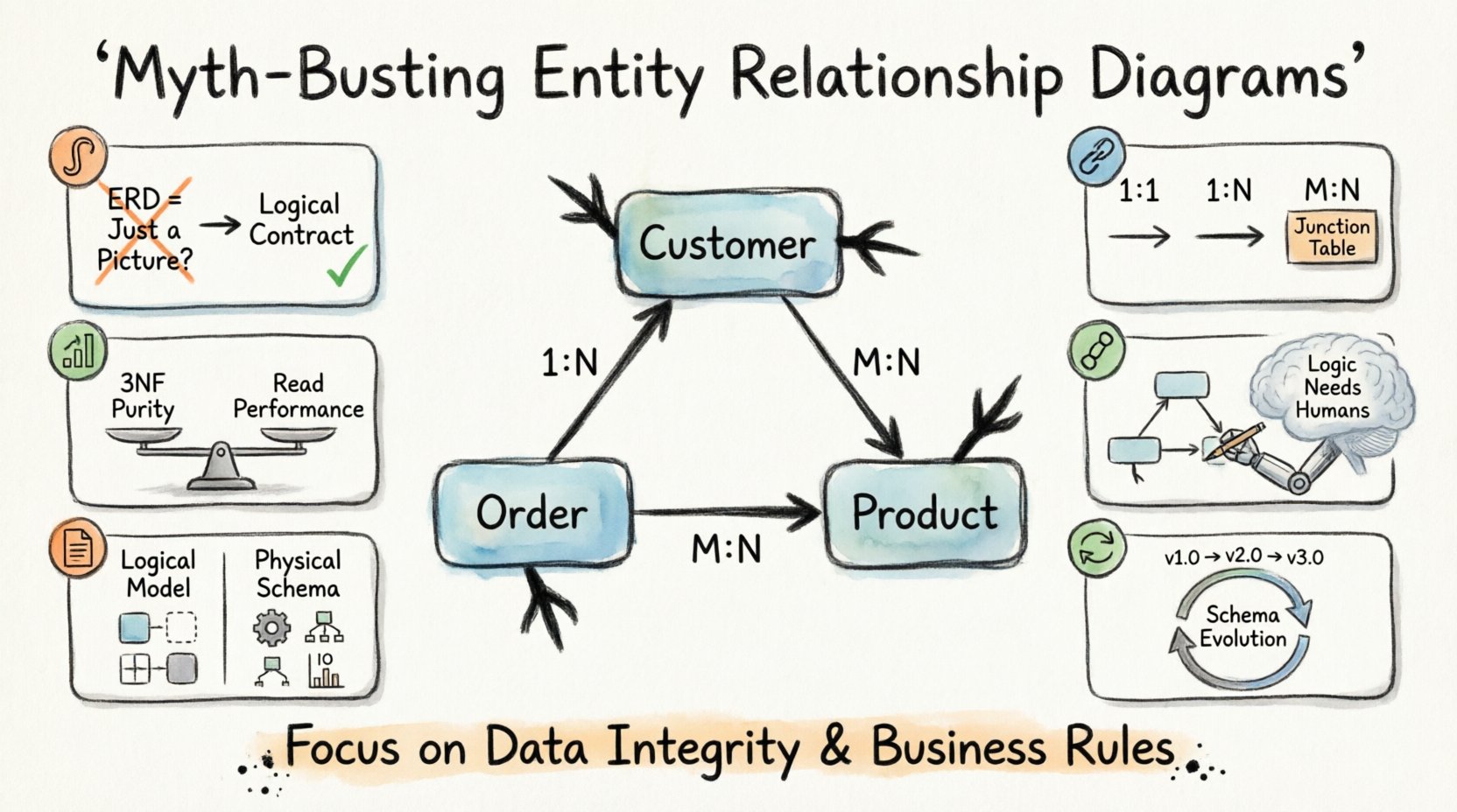
1. The Visual Trap: Is an ERD Just a Diagram? 🎨
One of the most pervasive myths suggests that an Entity Relationship Diagram is merely a documentation artifact. Many teams treat the diagram as a post-project deliverable, something created after the code is written to satisfy stakeholders. This view is fundamentally flawed. An ERD is a logical contract, not a picture.
When an ERD is treated as a visual afterthought, several risks emerge:
- Schema Drift: The database structure diverges from the intended design, leading to inconsistent data entry.
- Performance Bottlenecks: Queries fail because the underlying structure does not support the required joins efficiently.
- Data Integrity Loss: Foreign key constraints are ignored, allowing orphaned records to exist.
Consider the lifecycle of a database table. It begins with a business requirement. It moves to a logical model. It then becomes a physical schema. The ERD bridges the gap between the business logic and the technical storage. If the diagram is not the source of truth, the database will inevitably suffer from ambiguity.
Effective data modeling requires rigorous attention to detail. It is not about drawing boxes and lines. It is about defining the rules of engagement for data. Every line in an ERD represents a constraint. Every box represents a unit of data that must be preserved. Ignoring this reality leads to systems that are fragile and difficult to maintain.
2. Cardinality and Relationships: Beyond the Basics 🔗
Cardinality defines the numerical relationship between entities. It answers the question: How many instances of one entity relate to instances of another? Marketing materials often simplify this into one-to-many or many-to-many without explaining the implications.
Understanding cardinality is crucial for query performance and data consistency. There are three primary types of relationships:
- One-to-One (1:1): Each record in Table A relates to exactly one record in Table B. This is often used for security or data separation.
- One-to-Many (1:N): One record in Table A relates to multiple records in Table B. This is the most common relationship in transactional systems.
- Many-to-Many (M:N): Multiple records in Table A relate to multiple records in Table B. This requires a junction table to resolve physically.
A common misconception is that one-to-one relationships are always superior for data separation. While they offer isolation, they can introduce unnecessary complexity. Splitting data into two tables when a single table would suffice increases join overhead. This can degrade performance during read operations.
Conversely, ignoring many-to-many relationships can lead to data duplication. If you attempt to store a list of values in a single column without a proper junction table, you violate normalization rules. This makes updating and querying the data significantly harder.
| Relationship Type | Physical Implementation | Common Pitfall |
|---|---|---|
| One-to-One | Foreign Key in either table | Over-segmentation of data |
| One-to-Many | Foreign Key in the “Many” table | Circular reference errors |
| Many-to-Many | Junction table with two Foreign Keys | Missing unique constraints on junction |
When designing these relationships, you must consider the business rules. Does a customer have one address or many? Does a product belong to one category or many? The diagram must reflect the operational reality, not an idealized version of it.
3. Normalization: The 3NF Myth 📊
Normalization is a technique used to organize data to reduce redundancy. The Third Normal Form (3NF) is often cited as the gold standard. The myth suggests that every database must be fully normalized to 3NF to be considered valid. This is not always true.
Normalization eliminates anomalies. These are problems that occur during data insertion, update, or deletion. For example, if you store a customer name in every order record, changing the name requires updating thousands of rows. This is an update anomaly. Normalization fixes this by moving the name to a separate customer table.
However, strict adherence to 3NF can hurt performance. Every relationship requires a join. Joins are computationally expensive. In high-traffic reporting systems, excessive normalization can slow down query execution. This is where denormalization comes into play.
Denormalization is the intentional introduction of redundancy to improve read performance. It is a trade-off. You sacrifice write speed and storage efficiency for faster reads. This decision should never be made lightly. It requires a deep understanding of the access patterns.
Key considerations for normalization include:
- Read vs. Write Balance: Is the system read-heavy or write-heavy?
- Query Complexity: How complex are the reports required?
- Storage Costs: Is redundancy affordable?
Blindly following 3NF without analyzing the workload is a recipe for a sluggish application. The goal is to balance data integrity with performance requirements. Sometimes, a carefully denormalized view is the better solution than a perfectly normalized schema.
4. Tool Dependency: Automation vs. Logic 🤖
Modern tools offer features like automatic schema generation and reverse engineering. Vendors market these capabilities as time-savers. The myth here is that the tool can replace the designer. A diagramming tool can draw lines, but it cannot understand business context.
Automated generation often produces technically correct but logically flawed schemas. It may create tables based on code inspection rather than business requirements. It might miss hidden relationships that are not explicitly coded.
Human oversight is essential. The data modeler must validate the output against the actual needs of the organization. Key tasks that cannot be automated include:
- Defining Business Rules: Determining which attributes are mandatory.
- Handling Edge Cases: Deciding how to handle null values or soft deletes.
- Optimizing for Future Growth: Anticipating how the data will expand.
Tools are aids, not architects. They facilitate the creation of the diagram, but the logic resides in the human mind. Relying solely on automation leads to systems that are rigid and difficult to adapt. The tool should support the workflow, not dictate it.
5. The Physical Implementation Gap 📝
There is a distinct difference between a logical model and a physical model. The logical model describes entities and relationships conceptually. The physical model defines data types, indexes, and constraints.
Many teams assume the logical model translates directly to the physical database. This is rarely the case. Different database systems have different capabilities. A relationship that works well in one system might perform poorly in another.
For instance, data types vary. A field defined as “Text” in a logical model might need to be “VARCHAR(255)” or “TEXT” in the physical database. Indexing strategies also differ. An index that speeds up queries in one system might slow down writes in another.
When moving from design to implementation, you must adjust for the specific technology stack. Consider the following adjustments:
- Data Types: Ensure the chosen types match the storage engine.
- Indexes: Add indexes for frequently queried columns.
- Partitioning: Consider splitting large tables for better management.
- Constraints: Decide between application-level checks and database-level constraints.
Ignoring these differences leads to a gap between the design and the reality. The system may function, but it will not be optimized. A thorough review of the physical implementation is necessary to ensure the design holds up under load.
6. Maintenance and Evolution 🔄
Another significant myth is that a database design is static. Once the ERD is approved, it is set in stone. In reality, business requirements change. New features are added. Regulations evolve. The data model must evolve with them.
Refactoring a database is difficult. Changing a column type or relationship can break existing applications. Therefore, the design must be flexible enough to accommodate change without requiring a full rebuild. Strategies for maintainability include:
- Versioning: Track schema changes over time.
- Migration Scripts: Automate the deployment of changes.
- Documentation: Keep the diagram updated alongside the code.
Documentation is often neglected until it is too late. When a developer leaves the project, the knowledge of the data structure is lost. An up-to-date ERD serves as the primary reference for new team members. It reduces the learning curve and prevents errors.
Evolution requires discipline. Every change must be evaluated for its impact on existing data. Backward compatibility should be maintained whenever possible. This ensures that applications relying on the database do not break unexpectedly.
7. Common Myths vs. Reality Summary
To summarize the key points, we can categorize the most frequent misconceptions. This table provides a quick reference for distinguishing between marketing claims and technical facts.
| Myth | Reality |
|---|---|
| ERDs are just pretty pictures | ERDs are technical contracts defining data rules |
| More tables mean better design | Complexity reduces performance; balance is key |
| Normalization is always the goal | Denormalization improves read speed in specific cases |
| Tools can automate design | Tools assist, but logic requires human oversight |
| Logical models equal physical schemas | Physical implementation requires specific optimizations |
| Design is permanent | Schemas must evolve with business needs |
Final Thoughts on Data Modeling 🧭
Building a reliable database system requires a clear understanding of the underlying principles. Entity Relationship Diagrams are powerful tools when used correctly. They provide a shared language between business stakeholders and technical teams.
However, they are not magic. They do not solve data problems on their own. The value comes from the rigorous application of logic during the design phase. We must reject the notion that software tools can replace critical thinking. We must also accept that normalization is not a one-size-fits-all solution.
Success in database design depends on clarity, precision, and adaptability. By separating marketing hype from technical reality, you can build systems that are robust and scalable. Focus on the data integrity and the business rules. Let the diagram serve as the guide, not the destination.
When you approach data modeling with these principles in mind, the results speak for themselves. The system will be easier to maintain. Queries will run faster. Data will remain accurate. This is the true value of a well-constructed Entity Relationship Diagram.