In modern software engineering, understanding how components interact is critical for stability, scalability, and maintenance. As systems grow in complexity, the need for clear architectural documentation becomes paramount. The C4 model provides a structured approach to visualizing software architecture, moving from high-level context down to code-level details. Among these levels, the Container View holds a unique position. It serves as the bridge between business capabilities and the underlying infrastructure.
This guide explores how to effectively map infrastructure dependencies using the C4 Container View. We will discuss the principles of abstraction, the specific types of dependencies to document, and best practices for maintaining accuracy over time. By following these strategies, teams can ensure their architectural diagrams remain relevant and useful for decision-making.
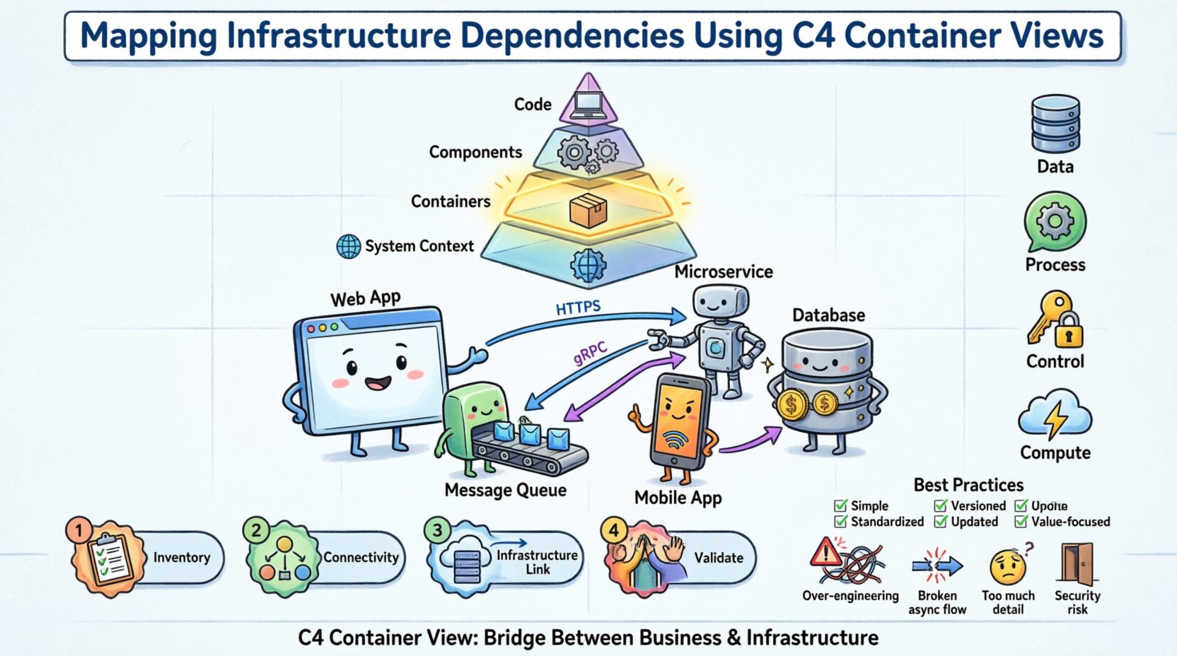
📚 Understanding the C4 Model Hierarchy
The C4 model organizes architecture documentation into four distinct levels. Each level serves a specific audience and provides a different level of detail. Understanding these levels is the prerequisite for correctly utilizing the Container View for infrastructure mapping.
Level 1: System Context 🌍
Defines the system as a whole and its relationship with users and other systems. This is the highest level of abstraction.Level 2: Containers 📦
Describes the high-level software building blocks within the system. A container is a deployed unit of software, such as a web application, a mobile app, or a database.Level 3: Components ⚙️
Breaks down containers into internal functional groups. This level focuses on how the code is structured internally.Level 4: Code 💻
Details specific classes, functions, or modules. This is rarely included in high-level architectural discussions.
When mapping infrastructure dependencies, the Container View (Level 2) is the most appropriate. It balances technical detail with business relevance. It allows architects to show how software components rely on infrastructure resources without getting bogged down in server configurations or code specifics.
🔍 The Container View Explained
A container in the C4 model represents a distinct, deployable unit of software. Common examples include:
A web application serving user requests.
A microservice handling specific business logic.
A database management system storing persistent data.
A mobile application running on a user device.
A batch processing job running on a schedule.
The Container View diagram visualizes these containers and the relationships between them. It answers the question: “How do the pieces of software work together to deliver functionality?”
Key Characteristics of a Container
Deployable: It can be independently built, tested, and deployed.
Executable: It runs code to perform tasks.
Technology Specific: It implies a technology stack (e.g., Java Spring Boot, Python Django, PostgreSQL).
Boundary: It has a clear interface that other containers can consume.
When creating these diagrams, it is essential to avoid listing every single server instance. Instead, group similar infrastructure into logical containers. For example, a “Web Server” container might represent a cluster of servers behind a load balancer, rather than drawing ten separate boxes for ten individual machines.
🌐 Mapping Infrastructure Dependencies
The core challenge in this task is linking the software architecture to the infrastructure it runs on. While the C4 model is primarily software-centric, infrastructure dependencies are the foundation upon which these software containers rest. Properly mapping these dependencies ensures that infrastructure changes do not break software functionality.
1. Distinguishing Logical vs. Physical Dependencies
One common mistake is conflating the software container with the physical hardware. A web application container runs on a server, but the diagram should primarily focus on the software boundary.
Aspect | Logical View | Physical View |
|---|---|---|
Focus | Functionality and interfaces | Hardware and network topology |
Example | API Gateway | Kubernetes Cluster / EC2 Instance |
Stability | High (changes rarely) | Low (changes frequently) |
Diagram Use | System Design | Deployment Planning |
In the context of the C4 Container View, we map the software container to the infrastructure resources required to support it. We do not replace the container with the server; we show the relationship.
2. Types of Infrastructure Dependencies
Dependencies in this context fall into specific categories. Identifying them correctly helps in planning for redundancy, security, and performance.
Data Dependencies: Where is data stored? This includes databases, object storage, and file systems. The container needs access to read and write data.
Process Dependencies: Does the container need to communicate with another process? This includes message queues, caching layers, and background workers.
Control Dependencies: Does the container rely on external authentication or authorization services? This includes identity providers and API keys.
Compute Dependencies: Does the container rely on external compute resources? This includes serverless functions or GPU instances.
3. Visualizing the Mapping
To map these dependencies effectively, the diagram should use clear conventions. Arrows indicate the direction of communication. Labels describe the protocol or data type. Infrastructure elements can be represented as boxes with specific styling to distinguish them from application containers.
For example, a “User Interface” container might connect to a “Backend API” container. The “Backend API” container then connects to a “Relational Database” container and a “Cache” container. Below these, you might indicate that the Database container resides on a specific infrastructure tier, such as a managed service or a dedicated cluster.
🛠️ Step-by-Step Methodology for Mapping
Creating an accurate map of infrastructure dependencies requires a systematic approach. Adhering to a process ensures consistency across different teams and projects.
Step 1: Inventory Existing Containers
Begin by listing all software containers within the system boundary. This list should include:
Web applications
API services
Database instances
Message queues
External system integrations
Do not include every microservice if the system is vast. Focus on the primary value streams. Group related services where appropriate to maintain clarity.
Step 2: Identify Connectivity Points
For each container, identify how it connects to others. Ask the following questions:
What protocols are used (HTTP, gRPC, TCP)?
What data is exchanged?
Is the connection synchronous or asynchronous?
Are there security requirements (TLS, authentication)?
This step helps define the dependencies clearly. It moves beyond “it connects to” to “it connects to via HTTPS with JWT authentication”.
Step 3: Link to Infrastructure Resources
Now, map the containers to the infrastructure. This does not mean drawing the physical servers. Instead, annotate the diagram to show infrastructure context.
Hosting Environment: Is the container running on-premise, in the cloud, or hybrid?
Network Segmentation: Is the container in a public subnet or a private VLAN?
Scaling: Does the container require auto-scaling?
Persistence: Is data stored in memory, on disk, or in a cloud object store?
Use notes or side annotations to convey this information without cluttering the main diagram. This keeps the visual hierarchy clean.
Step 4: Validate with Stakeholders
Once the diagram is drafted, review it with relevant teams. This includes DevOps, Security, and Development leads.
DevOps: Confirm infrastructure assumptions are accurate.
Security: Verify that sensitive data flows are correctly identified and protected.
Development: Ensure the logical flow matches the actual implementation.
This validation step is crucial. It catches discrepancies between the documented architecture and the actual deployment.
✅ Best Practices for Documentation
Maintaining architectural diagrams is often harder than creating them. To ensure long-term value, follow these best practices.
Practice | Why It Matters | How To Implement |
|---|---|---|
Keep It Simple | Complex diagrams are ignored. | Limit containers to 10-15 per diagram. Use zoom levels. |
Standardize Notation | Ensures everyone understands the symbols. | Use consistent shapes for databases, APIs, and users. |
Version Control | Tracks changes over time. | Store diagram source files in a code repository. |
Update on Change | Prevents stale information. | Link diagram updates to code pull requests. |
Focus on Value | Avoids documenting the obvious. | Only document dependencies that affect risk or cost. |
⚠️ Common Pitfalls to Avoid
Even experienced architects can fall into traps when mapping dependencies. Being aware of these common issues helps in producing higher quality documentation.
1. Over-Engineering the Diagram
Attempting to show every single dependency can make the diagram unreadable. If a container connects to a logging service, that might be assumed infrastructure and not worth a dedicated box unless the logging strategy is complex. Focus on the critical paths that impact system stability.
2. Ignoring Asynchronous Flows
Many modern systems rely on event-driven architectures. If you only draw request-response arrows, you miss the flow of events. Use different line styles or icons to represent asynchronous messages, queues, and streams.
3. Confusing Users with Infrastructure Details
The Container View is about software. If you draw the physical network switches, routers, or firewalls, you are moving into the Deployment View. Keep the infrastructure mapping high-level. Mention the type of infrastructure, not the specific IP addresses or hardware models.
4. Neglecting Security Boundaries
Dependencies often cross security zones. Failing to indicate where authentication or encryption is required can lead to security vulnerabilities. Clearly label connections that traverse public networks or require strict access controls.
🔄 Maintenance and Evolution
Architecture is not static. Systems evolve, dependencies shift, and infrastructure changes. A diagram that was accurate six months ago may be obsolete today. To maintain the integrity of the C4 Container View, adopt a living documentation strategy.
Automate Where Possible
Use tools that can generate diagrams from code or configuration files. This reduces the manual effort required to update the documentation. If the infrastructure code changes, the diagram can potentially update automatically.
Regular Reviews
Schedule periodic reviews of the architecture diagrams. During these reviews, verify that the diagram matches the current state of the system. Ask:
Are there new containers that have been added?
Have any containers been deprecated or removed?
Have the communication protocols changed?
Is the infrastructure mapping still accurate?
Integrate with CI/CD
Consider integrating diagram validation into the Continuous Integration pipeline. If a pull request changes the architecture significantly, trigger a check to ensure the documentation is updated. This creates a culture where documentation is treated as code.
📝 Checklist for Dependency Mapping
Before finalizing your C4 Container View diagram, run through this checklist to ensure completeness.
☐ Are all major software containers included?
☐ Is the direction of data flow clearly indicated?
☐ Are the protocols for communication labeled?
☐ Is the infrastructure context annotated (e.g., Cloud, On-Prem)?
☐ Are security boundaries and authentication methods noted?
☐ Is the diagram free of unnecessary technical clutter?
☐ Have the diagrams been reviewed by the operations team?
☐ Is the diagram stored in a central, accessible location?
🔗 Integrating with Other Views
The Container View does not exist in isolation. It connects to the System Context and the Component View. When mapping infrastructure dependencies, ensure consistency across these views.
System Context: Ensure the external systems shown here match the dependencies in the Container View.
Component View: Ensure the internal components map logically to the containers they reside in.
This alignment prevents contradictions. For instance, if a container is marked as “Cloud Only” in the Container View, the System Context should not show it running on an on-premise server. Consistency builds trust in the documentation.
💡 Final Thoughts
Mapping infrastructure dependencies using the C4 Container View is a vital skill for technical leaders and architects. It provides clarity on how software interacts with the environment that supports it. By following a structured approach, avoiding common pitfalls, and maintaining the diagrams over time, teams can create a living map of their architecture.
This clarity supports better decision-making regarding scalability, security, and cost. It reduces the risk of outages caused by undocumented dependencies. Ultimately, the goal is not to create perfect diagrams, but to create useful ones that help the team understand the system they are building and maintaining.
Start with the basics. Identify your containers. Map their connections. Annotate the infrastructure context. Review and refine. This iterative process will lead to robust architectural documentation that stands the test of time.