
Mastering System Architecture: Refining Use Cases with AI and VPasCode in PlantUML
In modern software engineering, the gap between conceptualizing system requirements and creating precise documentation is often bridged by model-driven development tools. One powerful approach to visualizing system behavior is the Use Case Diagram. When paired with the VPasCode tool within Visual Paradigm, developers can leverage the power of text-based modeling augmented by Artificial Intelligence.
This tutorial explores how to effectively utilize the AI modification feature to refine complex system diagrams, specifically focusing on a Food Delivery System architecture. We will walk through the underlying PlantUML syntax, the logic of actor relationships, and the workflow of issuing follow-up instructions to generate perfect diagrams.
Understanding the Foundation: PlantUML & VPasCode
Before diving into AI integration, it is crucial to understand the engine driving the visualization. PlantUML is a universal tool that allows users to create diagrams and visualizations using a simple text language. When integrated into Visual Paradigm as the VPasCode tool, it enables a seamless workflow where code on the left renders a diagram on the right.
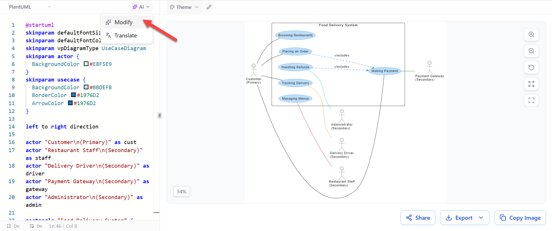
The code snippet visible in the editor demonstrates the setup for a vpDiagramType UseCaseDiagram. Here, the developer defines the visual style and the structural actors using specific syntax:
- skinparam: These directives control the aesthetics. For example, setting
BackgroundColor #E8F5E9defines the actor’s background, whileArrowColorstandardizes the connectors. - Actor Definition: The syntax
actor "Label" as aliascreates a human or external system interacting with the software. In our diagram, we see actors likecust(Customer) andstaff(Restaurant Staff). - Direction: The command
left to right directionensures the diagram flows logically from left to right, which is standard for most UML diagrams.
Decoding the Food Delivery System Architecture
The diagram on the right side of the interface visualizes the functional requirements of a Food Delivery Platform. It is structured to show how different user roles interact with specific system processes.
1. The Primary Actor: Customer
The Customer is the primary initiator of the system. Their interactions are mapped out through several key use cases:
- Browsing Restaurants: The initial step where users explore available options.
- Placing an Order: The core transactional use case.
- Tracking Delivery: A post-order monitoring feature.
- Handling Refunds: An exception handling process for failed transactions or quality issues.
2. The Secondary Actors
Complex systems rarely operate in isolation. This diagram highlights four critical secondary actors that support the system’s operations:
- Payment Gateway: An external system that validates financial transactions.
- Administrator: Responsible for system oversight and high-level management.
- Delivery Driver: The physical link between the restaurant and the customer.
- Restaurant Staff: The entity responsible for preparing and managing the menu.
3. Relationship Logic
The diagram utilizes specific UML relationships to define the flow:
- Includes (<
>): Notice the dotted line between Placing an Order and Making Payment. This indicates that the “Placing an Order” process cannot complete without the “Making Payment” process being executed. It is a mandatory dependency. - Associations: The solid lines connecting the Customer to the use cases represent direct interaction paths.
Step-by-Step: Refining the Diagram with AI
One of the most significant advantages of using the VPasCode tool is the ability to iterate on diagrams without manually rewriting complex syntax. The AI modification feature allows users to issue natural language instructions to update the model.
Step 1: Identify the Modification Need
Imagine you have created the initial draft of your Food Delivery System. You realize that the current scope is incomplete. Specifically, the Manager role needs to be added to oversee financial discrepancies, and the Refunds process requires a specific approval workflow.
Step 2: Access the AI Modification Feature
In the toolbar above the code editor, locate the AI dropdown menu. From the options provided, select Modify. This feature is designed to parse your existing PlantUML script and understand the current state of the diagram.
Step 3: Issue Follow-up Instructions
Instead of writing code, simply type your request in plain English. The AI engine will translate this into valid PlantUML syntax. Based on the system’s capabilities, you can issue commands such as:
- “Add a Manager actor and connect the Manager to the refund approval use case.”
- “Add an error path when payment fails.”
- “Group the use cases by customer, restaurant, and delivery operations.”
Step 4: Review and Render
Once the instruction is submitted, the tool automatically updates the code in the editor on the left and instantly renders the visual changes on the right. You can verify that the new actor appears and that the lines (associations) correctly connect to the new or modified use cases.
Best Practices for AI-Driven Modeling
To get the most out of the AI modification feature, consider the following technical strategies:
- Be Specific with Roles: When adding actors, specify if they are primary or secondary to maintain the correct visual hierarchy.
- Iterate on Logic: Use the AI to test system logic. For example, ask it to “Add an error path when payment fails” to visualize exception handling in your architecture.
- Standardize Naming: If the diagram becomes cluttered, ask the AI to “Rename ‘Process Order’ to ‘Validate and Confirm Order'” to align with your domain terminology.
- Refactor Layouts: You can request structural changes, such as converting a swimlane diagram into a standard non-swimlane activity diagram to simplify the view.
Conclusion
The evolution of diagramming tools has shifted the focus from manual drawing to strategic modeling. By utilizing the VPasCode tool, developers can maintain a single source of truth (the code) while benefiting from the rapid prototyping capabilities of AI. Whether you are adding a new actor, refining relationships, or restructuring the entire diagram, the AI modification feature ensures that your system architecture remains accurate, up-to-date, and visually consistent.