Designing a robust database schema requires precision. The Entity Relationship Diagram (ERD) serves as the blueprint for this structure, translating complex business logic into a visual format that developers and stakeholders can interpret. However, despite their utility, ERDs frequently become sources of misunderstanding during the modeling phase. Ambiguity in symbols, misinterpretation of cardinality, and confusion regarding attribute types can lead to significant rework later in the development lifecycle.
This guide provides a detailed examination of the specific components within an ERD that commonly cause friction among database architects and engineers. By clarifying the distinctions between strong and weak entities, dissecting relationship notations, and analyzing attribute classifications, we can reduce errors and ensure the resulting data model accurately reflects the operational requirements.
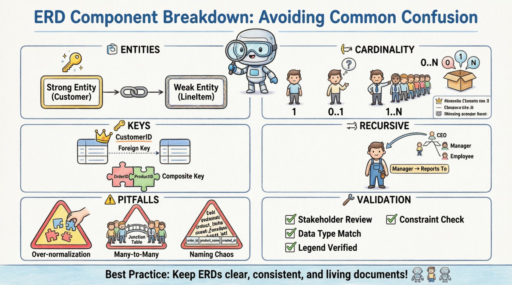
🏗️ Entity Types: Distinguishing Strong from Weak
At the core of any ERD are entities. These represent the objects or concepts about which data is stored. While most practitioners understand the concept of a table, the distinction between strong and weak entities is where the first major point of confusion often arises.
- Strong Entities: These entities possess their own primary key. They are independent and do not rely on other entities for identification. For example, a
Customerentity typically has a unique Customer ID, making it a strong entity. - Weak Entities: These entities cannot be uniquely identified by their own attributes alone. They rely on a relationship with another entity, known as the identifying parent, to exist. A
LineItemin an order system might exist only within the context of a specificOrder.
The confusion often stems from how these are visually represented. A strong entity is typically drawn as a standard rectangle. A weak entity is often depicted with a double rectangle. The failure to distinguish these visually can lead to database implementation errors where the weak entity table is created without the necessary foreign key constraints to enforce its dependency.
Implications of Misclassification
When a weak entity is modeled as strong, the database may allow records to exist without a parent. This creates orphaned data. Conversely, modeling a strong entity as weak forces unnecessary dependency, potentially limiting the entity’s usability outside of its primary context. It is crucial to determine if an object can exist independently before assigning it a strong entity status.
- Independence Check: Can this record exist without a link to another record?
- Identifier Source: Does the unique ID come from the entity itself or the relationship?
- Existence Dependency: Does deleting the parent automatically delete the child?
🔗 Relationship Cardinality and Optionality
Relationships define how entities interact. The cardinality specifies the number of instances of one entity that can or must associate with each instance of another entity. This is perhaps the most common area of confusion due to varying notation styles.
Cardinality Notations
There are multiple ways to denote cardinality on a diagram. Some use text labels like “1” or “N”, while others use crow’s foot notation. Mixing these styles or misinterpreting the symbols leads to logic gaps in the physical schema.
| Symbol / Label | Meaning | Example Scenario |
|---|---|---|
| 1 | Exactly one | A person has exactly one Social Security Number. |
| 0..1 | Zero or one | A person may have zero or one middle name. |
| 1..1 | One and only one | A project must have one Project Manager assigned. |
| 0..N | Zero to many | An Order can have zero or many Line Items. |
| 1..N | One to many | A Department must have one or many Employees. |
Optionality and Nullability
Optionality refers to whether a relationship is mandatory or optional. This directly impacts the foreign key definition in the database table. If a relationship is mandatory, the foreign key column cannot be null. If optional, it can be null.
Confusion often arises when the diagram shows a solid line versus a dashed line. Without a clear legend, developers may assume mandatory relationships where none exist, causing constraint violations during data entry. It is essential to document the meaning of line styles explicitly within the model documentation.
- Mandatory Relationship: The child record must exist for the parent record to be valid.
- Optional Relationship: The child record may be created without a parent, or the parent may exist without a child.
- Foreign Key Constraint: Must be set to
NOT NULLfor mandatory,NULLallowed for optional.
🔑 Attributes and Key Identification
Attributes are the properties of an entity. While seemingly simple, the classification of attributes into keys, foreign keys, and simple attributes causes frequent errors in normalization and query performance.
Primary vs. Foreign Keys
The Primary Key (PK) uniquely identifies a row. The Foreign Key (FK) links a row to a parent table. Confusion occurs when natural keys are used instead of surrogate keys, or when the PK is not consistently defined across the diagram.
- Natural Key: A key that exists naturally in the data, such as a Social Security Number or Email Address. These can change, leading to integrity issues.
- Surrogate Key: An artificial key generated by the system, such as an auto-incrementing integer. These are generally preferred for stability.
Composite Keys
A composite key consists of two or more columns that, taken together, uniquely identify a record. This is common in junction tables used to resolve many-to-many relationships. The confusion here lies in the order of the columns and which table holds the key.
If the order of columns in a composite key is not maintained consistently across related tables, joins will fail or require complex casting. It is vital to document the exact column sequence in the primary key definition.
🔁 Recursive Relationships
A recursive relationship occurs when an entity relates to itself. This is frequently used for hierarchical structures like organizational charts or bill of materials. The confusion stems from the visual representation, as the line connects the entity to itself.
Without clear labeling, it is often unclear which side of the relationship represents the parent and which represents the child. For example, in an Employee table, one employee manages another. The relationship must explicitly state that an Employee can be a Manager of other Employees.
- Self-Reference: The foreign key in the table points back to the primary key of the same table.
- Null Handling: The root of the hierarchy usually has a null value in the manager ID column.
- Depth Limitations: Recursive queries can become performance bottlenecks if the hierarchy is very deep.
⚠️ Common Modeling Pitfalls
Beyond specific elements, certain structural patterns often lead to confusion during implementation. Recognizing these pitfalls early prevents costly schema migrations.
1. Over-Normalization
While normalization reduces redundancy, over-normalization can make queries difficult to read and execute. Creating a separate table for every single attribute can fragment data unnecessarily. It is important to balance the third normal form (3NF) with practical query performance.
2. Many-to-Many Without Junction Tables
In a physical database, a many-to-many relationship cannot exist directly. It must be resolved into two one-to-many relationships using a junction table (associative entity). Forgetting this step results in a model that cannot be implemented in standard SQL.
- Logical vs. Physical: The logical model may show a direct line between two entities with cardinality N:N.
- Physical Implementation: This line must be split by a new table containing the foreign keys from both sides.
3. Inconsistent Naming Conventions
Using mixed naming styles (e.g., customer_id vs CustomerID vs customerId) creates confusion for developers writing queries. A standardized naming convention should be established at the start of the project.
- Lowercase with Underscores:
order_line_items - PascalCase:
OrderLineItems - CamelCase:
orderLineItems
🛠️ Validation Strategies
To ensure the ERD remains accurate and usable, specific validation steps should be taken during the review process. These steps help catch the confusion points before the schema is locked.
- Walkthrough with Stakeholders: Review the diagram with business users to ensure the relationships match their mental model of the workflow.
- Constraint Verification: Check that every foreign key has a corresponding primary key reference.
- Data Type Consistency: Ensure that attributes defined as integers in one table are not defined as strings in another.
- Legend Compliance: Verify that all symbols used in the diagram match the provided legend or standard.
📝 Summary of Best Practices
Maintaining clarity in an Entity Relationship Diagram requires discipline. By adhering to standard notation, clearly defining cardinality, and distinguishing between entity types, the risk of misinterpretation is significantly reduced. The goal is not just to draw a picture, but to create a specification that translates directly into a stable, reliable database system.
Remember that the diagram is a living document. As requirements change, the ERD should be updated to reflect those changes. This ensures that the data model continues to serve the business accurately over time. Regular reviews and adherence to the structural guidelines outlined in this article will help teams avoid the common pitfalls that derail database projects.