
In modern software engineering, clarity is often the most scarce resource. As systems grow in complexity, the cognitive load required to understand how different parts interact increases exponentially. Architects and developers frequently face the challenge of communicating the scope of a solution to stakeholders who may not be deeply technical. This is where the concept of defining system context boundaries becomes critical. It serves as the foundational layer for architectural documentation and strategic planning.
When creating a software solution, the first step is not writing code, but drawing the lines. These lines determine what is inside the system and what is outside. Establishing these boundaries clearly prevents scope creep, reduces ambiguity, and provides a stable reference point for future development. This guide explores the mechanics of defining these boundaries effectively, specifically within the context of structured modeling approaches like the C4 Model.
📐 Understanding the Role of the System Context Diagram
The system context diagram acts as the high-level map of your solution. It is the first view that stakeholders encounter when trying to grasp the architecture. Unlike detailed design documents, this view focuses on the interaction between the system and the world around it. It strips away internal complexity to reveal the essential relationships.
This level of abstraction serves several key purposes:
Communication: It allows non-technical stakeholders to understand what the system does without getting bogged down in implementation details.
Scope Management: It visually defines what is in scope for the project and what is considered external.
Dependency Identification: It highlights the critical connections required for the system to function.
Onboarding: New team members can quickly grasp the ecosystem in which they will be working.
Without a clear context diagram, teams often struggle with assumptions. One developer might assume a specific database is internal, while another treats it as an external service. These misunderstandings lead to integration errors and technical debt. A defined boundary removes this ambiguity by explicitly stating the limits of ownership and responsibility.
🎯 Identifying the Core System Boundary
Defining the boundary of the system itself is a decision-making process that requires careful consideration. The boundary is not necessarily a physical line in the code, but a logical separation of responsibility. It answers the question: “What does this specific solution control, and what does it rely on?”
When determining the core system, consider the following factors:
Business Ownership: Which business domain does this system directly serve? The system boundary often aligns with the functional ownership of a team or department.
Deployment Unit: Can the system be deployed independently? If the codebase can be released without requiring a synchronized update from another service, it likely represents a valid boundary.
Data Ownership: Does the system maintain its own persistent state? If the data is shared or managed by another entity, the boundary might need adjustment.
Failure Domain: If this system fails, does it take down the entire ecosystem? If yes, the boundary might be too broad.
It is common to encounter situations where the boundary is blurry. For example, should a reporting module be part of the core transaction system, or a separate reporting service? This decision impacts how data flows and how teams collaborate. A tighter boundary encourages specialized focus, while a looser boundary simplifies coordination. The goal is to find a balance that supports the current business needs without over-engineering for future scenarios.
👥 Cataloging External Actors
Once the core system is defined, the next step is identifying the actors. Actors are the entities that interact with the system. They are not part of the system itself, but they are essential to its operation. Misidentifying actors is a common source of architectural confusion.
Actors generally fall into three categories:
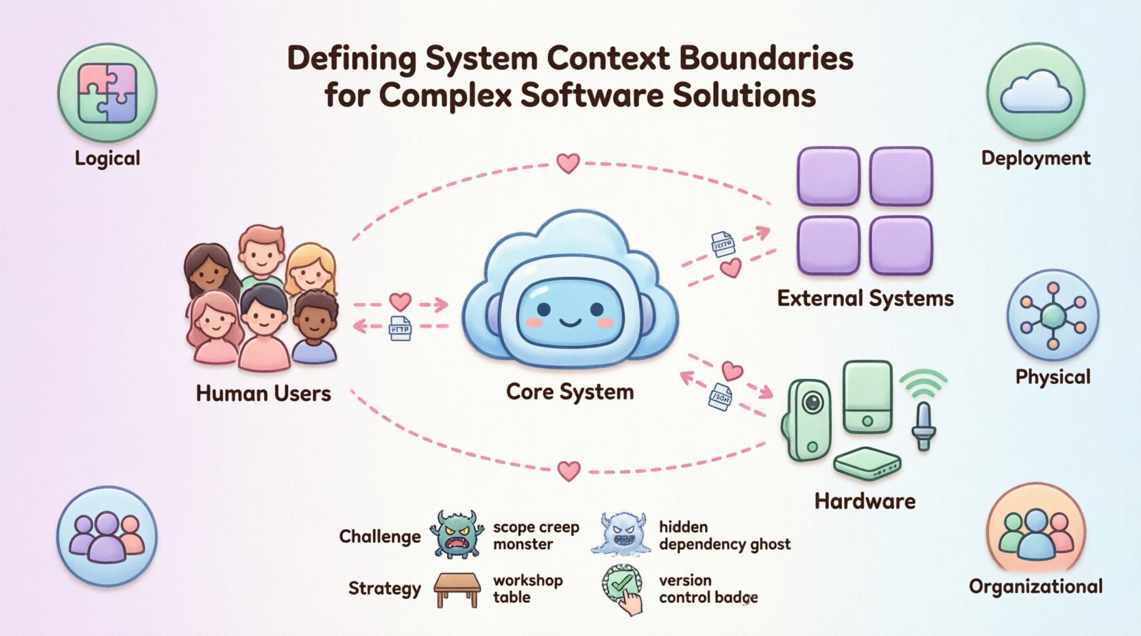
Human Users: These are the people who interact with the system directly. This includes administrators, end-users, or operators. Their role is to initiate actions or consume data.
External Systems: These are other software applications that the system communicates with. This could be a payment processor, a legacy database, or a third-party API. The system treats these as black boxes.
Hardware: In some contexts, physical devices are actors. This includes sensors, IoT devices, or specialized servers that host the application.
It is crucial to be precise when labeling actors. Instead of simply labeling a group as “Users,” specify the role. For instance, “Customer” is more useful than “User.” Similarly, when dealing with external systems, use the system name rather than generic terms like “Database” unless the specific database type is irrelevant. This precision helps in understanding the nature of the interaction.
🔗 Defining Interfaces and Data Flows
Boundaries are not just lines; they are gates. Data and requests flow through these gates. Defining the interfaces at the boundary is as important as defining the boundary itself. An interface defines the contract between the system and the actor.
Key considerations for interface definition include:
Protocol: Is the communication HTTP, TCP, or a message queue? The protocol dictates the nature of the interaction.
Direction: Is data flowing in, out, or both? Some actors only send data (e.g., a sensor), while others only consume it (e.g., an analytics tool).
Authentication: How is access controlled? Does the actor require an API key, OAuth token, or certificate?
Format: What data structure is exchanged? JSON, XML, or binary?
Documenting these details at the context level prevents downstream issues. If the interface is vague, developers will make assumptions that may conflict with the actual requirements. For example, assuming a data format is synchronous when it is actually asynchronous can lead to blocking issues in the architecture.
Boundary Type | Definition | Implication |
|---|---|---|
Logical Boundary | Defined by code modules or namespaces. | Easy to modify, but deployment may be coupled. |
Deployment Boundary | Defined by where the code runs. | Impacts scaling and infrastructure costs. |
Physical Boundary | Defined by network topology or hardware. | Impacts latency and security policies. |
Organizational Boundary | Defined by team ownership. | Impacts communication channels and decision speed. |
⚠️ Common Challenges in Boundary Definition
Even with a clear methodology, defining boundaries can be difficult. Teams often encounter specific pitfalls that degrade the quality of the architecture. Recognizing these challenges early allows for mitigation.
1. The Scope Creep Trap
As requirements evolve, the system boundary often expands. Features that were once “nice to have” become core requirements. Without strict governance, the system context diagram becomes outdated quickly. The solution is to treat the diagram as a living document that requires formal change control for boundary shifts.
2. Hidden Dependencies
Sometimes, a system relies on a service that is not immediately obvious. For example, a microservice might depend on a shared configuration store that is not shown in the diagram. This hidden coupling creates fragility. Every dependency must be explicit in the context view.
3. Over-Abstraction
Conversely, systems can be grouped too broadly. Grouping multiple distinct business domains into one “System” makes it impossible to understand the internal flow. If the system contains too many sub-domains, it is often better to split the boundary into multiple systems.
4. Implicit State
Dependencies based on implicit state are dangerous. If System A assumes System B is in a specific state, a change in System B breaks System A. Boundaries should enforce explicit state transfer. Data should be passed, not assumed.
🔄 Strategies for Iterative Refinement
Defining boundaries is rarely a one-time event. It is an iterative process that evolves as the system matures. The following strategies help maintain clarity over time.
Workshops: Conduct sessions with stakeholders to validate the boundary. Ask them to describe the system in their own words. If their description differs from the diagram, there is a gap in understanding.
Code Analysis: Use static analysis tools to identify actual dependencies. Compare these findings against the documented context diagram to ensure accuracy.
Feedback Loops: Encourage developers to flag discrepancies between the diagram and the code. Create a culture where the documentation is owned by the team, not just the architect.
Versioning: Version the diagrams alongside the code. This ensures that historical decisions can be traced back to a specific context view.
Refinement also involves pruning. If a connection to an external actor is rarely used, it should be reviewed. Removing unnecessary complexity from the context view reduces cognitive load and improves maintainability.
🔗 Connecting Context to Internal Design
The system context diagram is not an island. It serves as the anchor for lower-level diagrams. In structured modeling, the context view feeds into the container view. The containers are the major building blocks within the system boundary.
When moving from context to container, ensure consistency. The actors defined in the context diagram must map to the entry points of the containers. If an external system connects to the “System” in the context diagram, there must be a specific container within that system that exposes the interface.
This hierarchy ensures traceability. If a change is required in an external system, the impact can be traced from the context diagram down to the specific container and component. This traceability is vital for risk assessment and impact analysis.
📅 Maintenance and Version Control
Documentation drift is a silent killer of software architecture. Over time, the code changes, but the diagrams remain static. This leads to a disconnect between what the team thinks they are building and what they are actually building. To combat this:
Automate Generation: Where possible, generate diagrams from code annotations or configuration files. This reduces the manual effort required to keep them updated.
Review Cadence: Include diagram reviews in the sprint planning or architectural review meetings. Make it a standard part of the definition of done.
Change Logs: Maintain a log of boundary changes. Record why a boundary was moved or merged. This provides context for future architects.
Maintaining the system context is an investment. It pays dividends in reduced onboarding time, fewer integration bugs, and clearer decision-making. By treating the boundary as a first-class artifact, teams ensure that their software solutions remain understandable and manageable as they grow.
🧩 Handling Legacy Contexts
Not all systems start from a blank slate. Many organizations inherit legacy systems where the boundaries were never clearly defined. In these scenarios, the goal is to reverse-engineer the context without disrupting operations.
The approach involves:
Mapping Traffic: Analyze network logs and API gateways to identify active connections.
Interviewing Operators: Talk to the people who manage the system. They often know which external systems are critical.
Creating a “As-Is” View: Document the current state accurately, even if it is messy. This provides a baseline for refactoring.
Incremental Refactoring: Once the boundary is known, slowly decouple dependencies. Move the boundary to a cleaner state over time.
Legacy systems often suffer from “God System” syndrome, where everything is connected to everything. The goal here is not to fix it all at once, but to identify the core boundary and start isolating components. This gradual approach minimizes risk while improving clarity.
🛡️ Security and Boundary Considerations
Security is inextricably linked to boundaries. A boundary defines where trust ends and where verification begins. External actors should never be trusted implicitly. The boundary is the perimeter where security controls are enforced.
Key security considerations include:
Authentication at the Edge: Every request crossing the boundary should be authenticated. This prevents unauthorized access to internal components.
Data Minimization: Only pass the data required for the interaction across the boundary. Reducing data exposure reduces the impact of potential breaches.
Encryption: Data in transit across the boundary should be encrypted. This protects sensitive information from interception.
Rate Limiting: Boundaries are good places to enforce rate limits to prevent denial of service attacks from external actors.
By defining the boundary clearly, security teams can configure firewalls, proxies, and gateways more effectively. They know exactly what traffic to expect and what to block.
🏁 Final Thoughts on Architectural Clarity
Defining system context boundaries is a fundamental skill for any architect. It requires a balance between abstraction and precision. It demands that you understand not just the technology, but the business and the people involved. When done correctly, it creates a shared mental model that aligns the entire organization.
Complex software solutions do not need to be complex to understand. By drawing clear lines and documenting the interactions, you reduce the friction of development. This guide provides the framework to start that process. Remember that the diagram is a tool for thinking, not just a deliverable. Use it to question your assumptions and refine your design. In the long run, clarity wins over complexity every time.