Data Flow Diagrams (DFDs) serve as the blueprint for system logic, illustrating how information moves through a process. They are critical artifacts in system analysis and design, bridging the gap between business requirements and technical implementation. However, a diagram without validation is merely a sketch. To ensure architectural integrity, every DFD must undergo rigorous scrutiny.
This guide provides a comprehensive framework for validating Data Flow Diagrams. It focuses on structural consistency, logical correctness, and alignment with business rules. By following this checklist, analysts can prevent costly rework later in the development lifecycle.
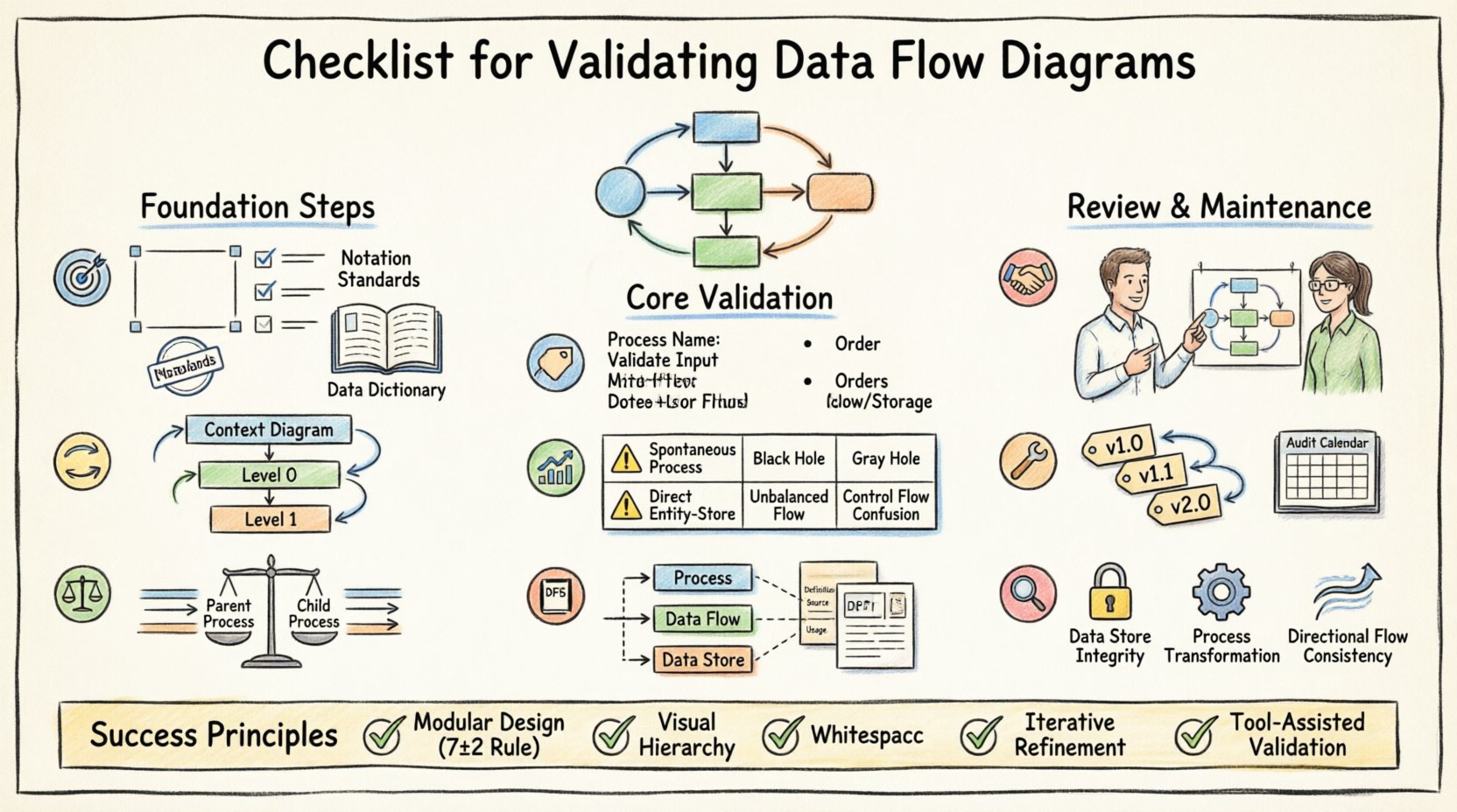
📋 Pre-Validation Preparation
Before examining the visual elements of the diagram, the context must be established. Validation cannot happen in a vacuum. The following prerequisites ensure the review process is effective.
- Define the System Boundary: Clearly identify what is inside the system and what is outside. External entities (sources and sinks) must be explicitly defined.
- Gather Requirements: Have the functional and non-functional requirements available. The diagram must map directly to these specifications.
- Establish Standards: Agree on notation standards (e.g., Gane & Sarson vs. Yourdon & Coad). Mixing notations creates ambiguity.
- Review Data Dictionary: Ensure a master list of data elements exists. The DFD cannot be valid if the data definitions are missing.
🔄 Hierarchy and Decomposition
DFDs are hierarchical. They start with a Context Diagram and decompose into Level 0, Level 1, and deeper levels. Validation requires checking the relationship between these layers.
1. Context Diagram Validation
The Context Diagram (Level -1) represents the system as a single process. It must be accurate before deeper levels are reviewed.
- Single Process Node: Verify there is exactly one process representing the entire system.
- External Entities: Confirm all external sources and destinations are present. Missing entities imply missing data flows.
- Data Flows: Ensure all inputs and outputs to the system are captured. No spontaneous data creation or destruction is allowed.
2. Level 0 and Decomposition
Level 0 breaks the single process into major sub-processes. This is where complexity begins.
- Process Count: Limit the number of processes to a manageable set (typically 5 to 9). Too many processes confuse the reader.
- Process Names: Names should be action-oriented (Verb + Noun), such as “Calculate Invoice” rather than “Invoice”.
- Data Stores: Identify where data is held at this level. Ensure no data store is connected directly to an external entity without a process in between.
⚖️ Balancing Rules
One of the most common errors in DFD creation is violating the balancing rule. This rule dictates that the inputs and outputs of a parent process must match the inputs and outputs of its child processes exactly.
- Input Conservation: If a parent process receives “Customer Order,” the child processes must collectively receive “Customer Order.” No new inputs can appear in the child level that were not in the parent.
- Output Conservation: If a parent process sends “Invoice,” the child processes must collectively send “Invoice.” No outputs can disappear or appear unexpectedly.
- Flow Verification: Trace every line entering the parent process. Trace every line leaving the parent process. Verify they exist in the child diagram.
- Store Consistency: Data stores accessed at the parent level must be accessible at the child level if data is being written or read there.
Failure to balance leads to a disconnect between the high-level view and the detailed implementation. It often results in developers building features that were not scoped or ignoring critical data requirements.
🏷️ Naming Conventions
Consistency in naming is vital for readability and maintenance. Ambiguous names lead to misinterpretation of system behavior.
- Processes: Always use a verb followed by a noun. Avoid single words. Correct: “Update Stock.” Incorrect: “Stock Update”.
- Data Flows: Use singular nouns. Correct: “Item.” Incorrect: “Items”.
- Data Stores: Use plural nouns. Correct: “Orders.” Incorrect: “Order”. External Entities: Use proper nouns or business terms. Correct: “Customer.” Incorrect: “User”.
📊 Common Errors and Validation Risks
Even experienced analysts make mistakes. The following table outlines frequent violations and their potential impact on the system architecture.
| Check Category | Validation Criteria | Risk if Ignored |
|---|---|---|
| Spontaneous Processes | Every process must have at least one input flow. | Data is created from nothing, violating system logic. |
| Black Holes | Every process must have at least one output flow. | Data is consumed without result, indicating a logic gap. |
| Gray Holes | Input and output data content must match. | Data is transformed without clear definition of the transformation. |
| Direct Entity-to-Store | No data flow connects an entity directly to a data store. | Bypasses business rules and validation logic. |
| Unbalanced Flows | Parent and child flows must match. | Architecture drift; implementation does not match design. |
| Control Flows | DFDs show data, not control signals. | Confusion between data movement and system triggers. |
📚 Alignment with Data Dictionary
A Data Flow Diagram is only as good as the data definitions supporting it. The Data Dictionary is the repository of metadata that defines the structure of every data flow and store.
- Data Element Consistency: Check if the data elements named in the DFD exist in the Data Dictionary.
- Data Structure: Verify the composition of data flows. Does “Customer Order” include “Customer ID” and “Order Date” as defined?
- Unique Identifiers: Ensure primary keys are identified in data stores to support data integrity.
- Aliases: If a data element has multiple names across the documentation, standardize them to avoid confusion.
- Data Types: Validate that the data types (numeric, string, date) are consistent between the diagram and the database schema.
🤝 Stakeholder Review and Sign-off
Technical accuracy is not enough. The diagram must be understood by the business stakeholders who provided the requirements.
- Business Terminology: Do not use technical jargon in the labels. Use the language the business uses.
- Walkthroughs: Conduct a walkthrough session where stakeholders trace the flow of data for a specific transaction.
- Gap Analysis: Ask stakeholders if any critical business activities are missing from the diagram.
- Validation Sign-off: Obtain formal approval. This confirms that the diagram accurately reflects the agreed-upon business logic.
🛠️ Maintenance and Version Control
Systems evolve. Requirements change. A DFD that is valid today may be invalid tomorrow. Maintenance is part of the validation lifecycle.
- Change Management: Any change to the process logic requires an update to the DFD. Do not update code without updating the diagram.
- Versioning: Label diagrams with version numbers and dates. Maintain a history of changes to understand the evolution of the system.
- Linkage: Link the DFD to the requirements document. If a requirement changes, the corresponding diagram node must be flagged.
- Periodic Audit: Schedule regular reviews of the DFDs against the actual system behavior. Drift occurs over time.
🔍 Detailed Technical Consistency Checks
Beyond the general rules, specific technical constraints must be observed to ensure the diagram is ready for implementation.
1. Data Store Integrity
Data stores represent persistent storage. They should not be transient.
- Read/Write Access: Verify that every process writing to a store also reads from it if necessary. Ensure no process writes to a store without a read requirement if data modification is involved.
- Open/Closed Boundaries: Data stores should not have open boundaries. Every data store must be connected to at least one process.
- Store Naming: Names should reflect the content, e.g., “Employee Files” rather than “File 1”.
2. Process Logic Completeness
Processes represent transformation logic.
- Transformation: Ensure the process actually changes the data. A process that simply passes data through is a flow, not a process.
- Decision Points: While DFDs do not show decision logic explicitly (like flowcharts do), the flow labels should imply conditions if necessary (e.g., “Valid Order” vs “Invalid Order”).
- External Dependencies: If a process relies on an external system, it should be represented as an external entity or a subprocess, not a magic box.
3. Flow Directionality
Arrows indicate the direction of data movement.
- Single Direction: Arrows must point from source to destination. Do not use double-headed arrows unless the data flow is truly bidirectional in the same step.
- Label Clarity: Every arrow must have a label. Unlabeled flows are ambiguous.
- No Crossing: Minimize crossing lines. If lines cross, use a crossover symbol or restructure the layout to improve readability.
🧠 Cognitive Load Reduction
A valid DFD is not just technically correct; it must be cognitively accessible. If the diagram is too complex, it fails its primary purpose: communication.
- Modularity: Break complex processes into subprocesses. If a process has more than 7 inputs or outputs, decompose it.
- Visual Hierarchy: Use consistent shapes for processes, diamonds for data stores (depending on notation), and rectangles for entities. Consistency reduces cognitive load.
- Whitespace: Allow space between elements. Cluttered diagrams hide errors.
- Color Coding: Use color to distinguish between different types of flows (e.g., input vs. output) if the tool allows, but ensure black and white printing remains legible.
📝 Final Considerations
Validation is an iterative process. It rarely succeeds on the first pass. The goal is to build a model that is robust, clear, and aligned with reality.
- Iterative Refinement: Expect to revise the diagram multiple times. Each revision should increase clarity.
- Documentation Hygiene: Keep the diagram synchronized with the documentation. If the text says one thing and the diagram says another, the system will fail.
- Training: Ensure the team understands the notation. A checklist is useless if the reviewers do not understand the symbols.
- Tooling: Use modeling tools that enforce syntax rules. While the checklist is manual, tools can automate basic checks like balancing.
By adhering to this comprehensive checklist, you ensure that the Data Flow Diagrams serve as a reliable foundation for the system. They become a living document that guides development and validates business logic. This discipline reduces risk, improves communication, and ensures the final product meets the intended requirements.
Remember that the diagram is a tool for thinking, not just a deliverable. The act of validating the diagram forces the analyst to confront logical gaps that might otherwise remain hidden until testing begins. Take the time to validate thoroughly.