Software architecture is often described as the backbone of a project, yet it remains one of the most misunderstood aspects of development. Teams frequently struggle to align on how different parts of a system connect, what responsibilities each part holds, and how changes ripple through the infrastructure. Misalignment leads to technical debt, duplicated effort, and frustrated stakeholders.
This is where the C4 Model steps in. It offers a structured approach to visualizing software architecture, providing a common language for developers, architects, and business stakeholders. By breaking down complex systems into manageable layers, the C4 Model transforms abstract code into clear, communicable diagrams. This guide explores how adopting this framework improves collaboration, reduces ambiguity, and streamlines the development lifecycle.
🤔 The Communication Challenge in Software Development
Before diving into the solution, it is important to understand the problem. In modern engineering environments, teams are often distributed, cross-functional, and working on different timelines. A frontend developer might have a different mental model of a backend service than the engineer who built it. A product manager might envision a feature differently than the database architect.
Common communication breakdowns include:
- Missing Context: Junior developers join a project and cannot find documentation that explains why a system was built a certain way.
- Overwhelming Detail: Diagrams that show every single class and method overwhelm non-technical stakeholders.
- Outdated Information: Documentation that is not updated alongside the code creates a “docs rot” problem, where trust in the documentation erodes.
- Inconsistent Notation: One team uses sequence diagrams while another uses flowcharts, making it hard to stitch together a holistic view.
Without a standardized approach, these issues compound. The C4 Model addresses these pain points by enforcing a hierarchy of abstraction. It dictates what level of detail is appropriate for specific audiences, ensuring that everyone sees the information they need without getting lost in the noise.
🧩 Understanding the C4 Model Levels
The C4 Model consists of four distinct levels, each representing a different degree of zoom. This hierarchy allows teams to navigate from the high-level business context down to the specific code structures without losing the thread of the narrative. It is not about creating four separate documents, but rather four views of the same system.
Here is a breakdown of the four levels:
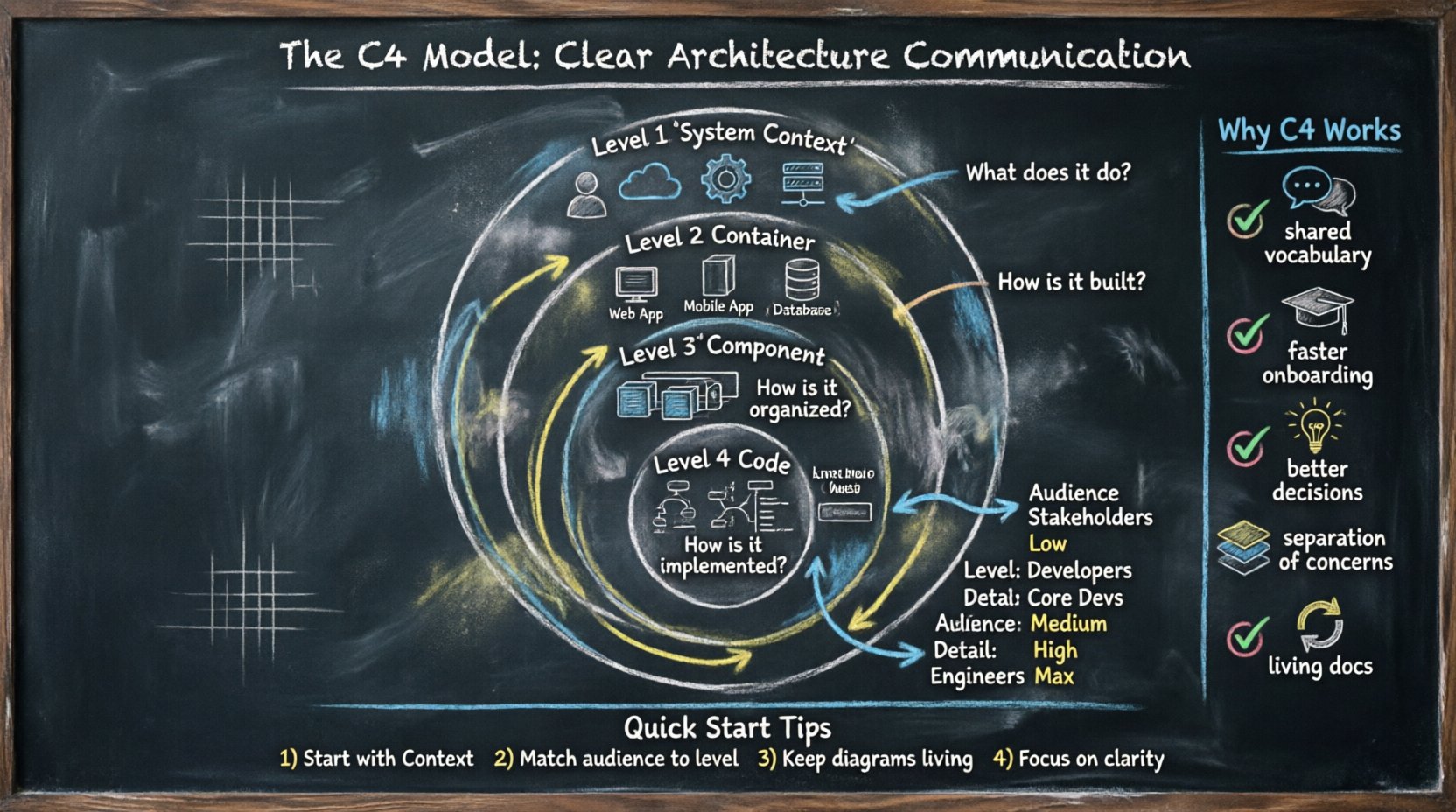
1. System Context Diagram (Level 1)
This is the broadest view. It shows the system in question and the people and other systems that interact with it. It answers the question: “What does this system do, and who uses it?”
- Focus: Boundaries of the system.
- Audience: Stakeholders, managers, new hires.
- Detail: Low. Only external entities and connections.
2. Container Diagram (Level 2)
Zooming in, this level shows the high-level technical building blocks. Containers are distinct, deployable units of software, such as a web application, a mobile app, a microservice, or a database. It answers: “How is the system built technically?”
- Focus: Technology stack and major components.
- Audience: Developers, system architects.
- Detail: Medium. Shows interactions between containers.
3. Component Diagram (Level 3)
Drilling down further, this view breaks down a single container into its constituent parts. A component is a logical grouping of functionality, such as a specific module within a service or a library. It answers: “What are the internal building blocks of this container?”
- Focus: Internal structure of a container.
- Audience: Core developers, technical leads.
- Detail: High. Shows relationships between components.
4. Code Diagram (Level 4)
This is the deepest level, mapping to the actual source code. It shows classes, interfaces, and methods. It answers: “How is this functionality implemented in code?”
- Focus: Implementation details.
- Audience: Individual contributors.
- Detail: Maximum. Often generated automatically or used for specific debugging.
Comparison of C4 Levels
| Level | Name | Primary Audience | Key Question |
|---|---|---|---|
| 1 | System Context | Business & Stakeholders | What does the system do? |
| 2 | Container | Developers & Architects | How is it built? |
| 3 | Component | Core Developers | How is it organized? |
| 4 | Code | Engineers | How is it implemented? |
📉 Why Standard Diagrams Fail Collaboration
Before the C4 Model gained traction, teams relied on various ad-hoc diagramming styles. While well-intentioned, these often lacked structure. Here is why traditional approaches often fall short in a team setting:
- Too Much Detail Too Soon: Jumping straight into class diagrams confuses business stakeholders. They do not care about variable names or method signatures; they care about value delivery.
- Too Little Detail for Engineers: High-level architecture diagrams often omit critical technical decisions, leaving engineers guessing about interfaces and data flows.
- Lack of Standardization: Without a shared vocabulary, one team calls a “service” a “microservice” while another calls it an “API.” This semantic drift creates confusion.
- Static Snapshots: Static images are often treated as final products rather than living documents, leading to rapid obsolescence.
The C4 Model mitigates these issues by enforcing a strict separation of concerns. It forces the team to decide what belongs at each level, preventing the “kitchen sink” diagram that tries to show everything at once.
✅ Benefits of Adopting C4 for Collaboration
Implementing this structured modeling approach yields tangible benefits beyond just pretty pictures. It fundamentally changes how information flows through the organization.
1. Shared Vocabulary
When everyone agrees that a “Container” is a deployable unit and a “Component” is a logical grouping, discussions become faster. There is no need to define terms repeatedly. This shared language reduces the cognitive load during meetings and code reviews.
2. Improved Onboarding
New team members often struggle to understand the architecture of a large codebase. With C4 diagrams, a new developer can start at the System Context level to understand the business domain, then zoom in to Containers to see the tech stack, and finally to Components to understand the logic. This scaffolded learning path is significantly more effective than reading raw code.
3. Better Decision Making
When planning a new feature, architects can use the C4 Model to visualize the impact. If a change affects a Container, they know to check the Component diagrams for dependencies. This prevents scope creep and ensures that technical debt is identified early.
4. Separation of Concerns
Not everyone needs to see the Code level. By separating views, the team avoids information overload. Stakeholders stay focused on business value, while engineers focus on implementation details. This respects the time and attention of different roles.
5. Documentation Maintenance
Because the model is structured, it is easier to keep up to date. If a new microservice is added, the Container diagram needs updating. If a new module is created, the Component diagram changes. This modular approach makes documentation feel less like a burden and more like a natural part of the development workflow.
🛠️ Practical Steps for Implementation
Adopting the C4 Model is not about buying a specific tool or forcing a rigid process. It is about shifting mindset. Here is a practical roadmap for introducing this model to a development team.
Step 1: Secure Buy-In
Start by explaining the “why” to the team. Demonstrate how the current communication gaps are causing delays. Show examples of how C4 can clarify these issues. Ensure that leadership understands that this is a communication tool, not just a drawing exercise.
Step 2: Establish Standards
Define what constitutes a valid diagram. Agree on naming conventions. For example, should containers be named after the technology (e.g., “Java App”) or the function (e.g., “Order Service”)? Consistency is key for readability. Decide on the tools to be used for diagramming, ensuring they support version control if possible.
Step 3: Start with the Context
Do not start with the code. Start with the System Context diagram. Get the stakeholders to agree on the boundaries of the system and the external dependencies. This ensures alignment on the business scope before technical details are discussed.
Step 4: Iterate and Refine
Drawings will evolve. That is okay. Encourage the team to update diagrams when the architecture changes. Treat diagrams as code: they should be reviewed and versioned. This prevents the documentation from becoming stale.
Step 5: Integrate into Workflows
Link diagrams to the codebase. If a pull request modifies a container, the diagram should be updated as part of the acceptance criteria. This ensures that the documentation remains synchronized with the implementation.
🔄 Integrating C4 into Agile Workflows
Agile methodologies emphasize speed and adaptability. Some teams worry that creating diagrams slows down delivery. However, when integrated correctly, the C4 Model accelerates agility by reducing rework and miscommunication.
Consider how this fits into standard Agile ceremonies:
- Sprint Planning: Use Component diagrams to discuss the scope of work. Developers can identify dependencies on other components before committing to tasks.
- Daily Standups: If a blocker involves a system interaction, refer to the Container diagram to clarify the integration point.
- Retrospectives: Review the diagrams. Are they still accurate? Is there a part of the system that is poorly documented? Plan to address it in the next sprint.
- Architecture Reviews: Use the diagrams as the primary artifact for review. This focuses the discussion on structure and design rather than syntax or style.
By treating diagrams as living artifacts, the team maintains a balance between documentation and delivery. The goal is not perfection, but clarity.
🚫 Common Pitfalls and How to Avoid Them
Even with the best intentions, teams can stumble when adopting new modeling practices. Being aware of common traps helps avoid them.
Pitfall 1: Over-Modeling
Trying to document every single class or method at the Code level for every service is unsustainable. It creates more work than it saves.
Solution: Limit Code level diagrams to complex or critical areas. Use text descriptions for simpler logic.
Pitfall 2: Ignoring the Audience
Creating a detailed Component diagram and showing it to a Product Manager who just wants to know the timeline.
Solution: Tailor the view. Use the appropriate level for the specific meeting or audience.
Pitfall 3: Treating Diagrams as Static
Creating a diagram once and never updating it again. This leads to “docs rot.”
Solution: Make diagram updates part of the Definition of Done for relevant tasks.
Pitfall 4: Tool Fetishism
Focusing too much on the specific software used to draw diagrams rather than the content.
Solution: Choose a tool that is easy to use and maintain. The value is in the model, not the renderer.
📊 Measuring the Impact on Team Efficiency
How do you know if the C4 Model is actually helping? You need to look at qualitative and quantitative indicators.
- Onboarding Time: Track how long it takes new developers to become productive. A reduction suggests better documentation.
- Meeting Duration: If architecture meetings are shorter but more productive, the shared understanding is improving.
- Defect Rate: If fewer bugs are introduced due to integration misunderstandings, the architectural clarity is paying off.
- Team Sentiment: Survey the team. Do they feel less confused about system boundaries? Do they feel more confident making changes?
Remember, the goal is not to measure the number of diagrams created, but to measure the quality of communication enabled by them.
🌐 The Future of Architecture Communication
As software systems become more distributed and complex, the need for clear communication grows. Cloud-native architectures, microservices, and serverless functions introduce new layers of abstraction. The C4 Model provides a stable foundation amidst this complexity.
It allows teams to scale their communication processes alongside their code. Whether a team is building a monolith or a distributed ecosystem, the principles of Context, Containers, Components, and Code remain relevant. By focusing on the hierarchy of information, teams can ensure that the right people see the right details at the right time.
Ultimately, the C4 Model is not just about drawing boxes and arrows. It is about respecting the cognitive limits of your audience and providing a structured way to share knowledge. When developers, architects, and business owners speak the same language, the result is software that is built faster, maintained easier, and understood better by everyone involved.
🔑 Key Takeaways for Your Team
To wrap up, here are the essential points to remember when implementing this approach:
- Start with the Why: Focus on communication gaps, not just diagramming.
- Respect the Hierarchy: Do not mix levels of detail in a single view.
- Keep it Living: Update diagrams as part of the development process.
- Match the Audience: Use the System Context for business and Components for engineers.
- Focus on Clarity: Simplicity is more valuable than comprehensiveness.
By adopting these practices, development teams can transform their architecture documentation from a chore into a strategic asset. The result is a culture of clarity, where technical decisions are transparent and collaboration is seamless.