
From Text to Visuals: Mastering System Modeling with VPasCode
In the modern landscape of software engineering and business analysis, the gap between abstract ideas and concrete visual representations is often bridged by a tedious manual process. Historically, creating a Use Case Diagram or a System Architecture map required the user to navigate complex GUIs, drag and drop elements, and meticulously align connectors. However, a paradigm shift is occurring with the advent of Diagram-as-Code technologies. This tutorial explores the transformative capabilities of the VPasCode tool, demonstrating how natural language descriptions can be instantly converted into professional-grade system diagrams.
The Architecture of VPasCode
VPasCode, developed by Visual Paradigm, represents a significant evolution in modeling tools. Unlike traditional diagramming software that relies heavily on mouse interaction, VPasCode is built on a text-based architecture. This approach leverages the power of code to define the structure, style, and logic of a diagram.
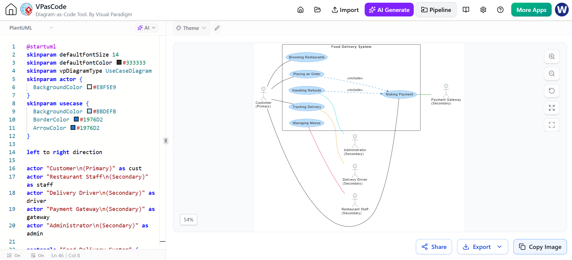
The interface, as seen in the system capture, is split into a dual-pane layout:
- The Source Editor (Left): This is where the magic happens. Users write code in a specific syntax (such as PlantUML). This area supports syntax highlighting and specific directives for skin parameters and actor definitions.
- The Visual Canvas (Right): This pane renders the code in real-time. As the user types or modifies the text, the diagram updates instantly, providing immediate visual feedback.
Understanding the Syntax: A Step-by-Step Breakdown
To master VPasCode, one must understand the underlying syntax that drives the rendering engine. Let us deconstruct the code snippet provided in our example, which generates a comprehensive Food Delivery System Use Case Diagram.
1. Setting the Stage: Skin Parameters
Before defining actors or use cases, the diagram’s aesthetic is controlled via skinparam directives. These lines of code act as global style variables, ensuring a consistent look and feel across the entire diagram.
For example, in the provided source:
skinparam defaultFontSize 14: Establishes a standard readability size.skinparam vpDiagramType UseCaseDiagram: Explicitly tells the engine that we are building a Use Case Diagram, not a Class or Sequence diagram.skinparam actor: This block customizes the appearance of the stick figures (actors), setting specific background colors (#E8F5E9) to distinguish them from the background.
2. Defining the Cast: Actors
Every system has external entities interacting with it. In VPasCode, these are defined as actor blocks. The code snippet utilizes a “left to right” direction, organizing the actors spatially.
actor "Customer (Primary)" as cust actor "Restaurant Staff (Secondary)" as staff actor "Delivery Driver (Secondary)" as driver
The use of
allows for line breaks within the actor’s label, and the as keyword assigns a unique alias (e.g., cust) that can be referenced later to draw connections. This method is far less prone to human error than manually typing labels via a GUI.
3. The Core Logic: Use Cases and Relationships
The heart of the diagram lies in defining the functions (ovals) and their interactions. The code defines use cases like Browsing Restaurants and Placing an Order.
The relationships are expressed through simple, readable lines:
- Standard Association:
cust --> Browsing Restaurantsindicates a direct interaction between the Customer and the system function. - Inclusion: The code uses
Placing an Order ..> Making Payment : «includes». This demonstrates the power of modeling complex logic. In a real-world scenario, “Making Payment” is a mandatory sub-process required to complete “Placing an Order.” VPasCode renders this as a dashed arrow with the specific stereotype label.
Reviewing and Refining Generated Source
One of the most critical steps in the modeling process is the review phase. When using AI-assisted tools or code-based modeling, the output is not always perfect on the first try. The generated source code serves as a transparent blueprint.
By inspecting the text on the left, a user can quickly spot errors in logic or styling. For instance, if an arrow is pointing the wrong way, or if a color code is incorrect, it can be fixed by simply editing the text. This contrasts sharply with traditional tools where fixing a layout issue might involve dragging multiple disconnected nodes and reshuffling the entire canvas.
Key Takeaways for Modelers
- Version Control Friendly: Because the diagram is essentially a text file, it can be stored in Git repositories, allowing teams to track changes over time.
- AI Integration: As noted in the interface, VPasCode features an “AI Generate” button. This allows users to input a natural-language description (e.g., “Create a use case for a food delivery app”), and the AI translates it into the structured code we reviewed above.
- Visual Clarity: The resulting diagram clearly separates the system boundary from the external actors, making the scope of the system immediately apparent to stakeholders.
Conclusion
The transition from manual drag-and-drop to code-driven modeling represents a maturation of software design tools. It brings the precision of programming to the creativity of diagramming. By mastering the syntax of VPasCode, analysts can create complex, accurate, and maintainable system models with unprecedented speed.
For teams looking to standardize their documentation and reduce the overhead of diagram maintenance, the Visual Paradigm VPasCode Tool is the recommended tooling for implementing this modern, efficient approach to system architecture.