

Mastering UML Inheritance: 7 Critical Differences Between Shape Class Diagram Styles
When modeling complex object-oriented systems, few concepts are as fundamental yet as frequently misunderstood as inheritance. Visual Paradigm’s documentation on the Shapes inheritance example reveals a crucial truth for system architects: while the visual representation of inheritance can vary, the underlying semantic logic remains constant.
Whether you are migrating legacy code or designing a new microservices architecture, understanding how to visualize the “Is-A” relationship correctly is the difference between a clear model and a confusing mess. This article breaks down the nuances of UML class diagram inheritance, specifically analyzing the two distinct styles presented in the standard Shapes example.
1. The 2 Distinct Visual Styles for UML Inheritance
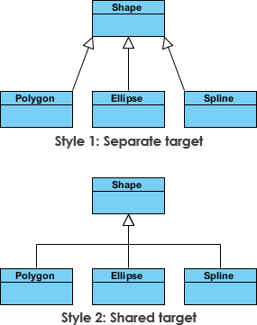
The visual representation of inheritance in UML is not monolithic. As demonstrated in the Shapes hierarchy example, there are two primary approaches to drawing the connector between a superclass and its subclasses. Both are semantically equivalent, but they serve different modeling needs.
- The Closed Triangle (Standard Notation): This is the most widely recognized UML notation. It features a solid line connecting the subclass to the superclass, terminating in a hollow (unfilled) triangle pointing toward the parent class. This style is the industry standard for high-level architectural diagrams and is preferred by Visual Paradigm for its clarity and strict adherence to UML 2.x specifications.
- The Open Arrow (Alternative Notation): In some modeling contexts or legacy tools, you may encounter a solid line ending in an open arrowhead pointing to the superclass. While technically a variation often seen in older diagrams or specific tool defaults, it conveys the exact same “generalization” relationship as the closed triangle. In the Shapes example, this style is used to demonstrate that visual variance does not alter semantic meaning.
2. Core Components of the Shapes Inheritance Hierarchy
To understand how these styles function in practice, we must dissect the specific elements of the Shapes example. This hierarchy is a classic example of polymorphism and abstraction in action.
- The Abstract Base Class: At the top of the hierarchy sits the Shape class. This acts as the superclass or parent, defining common attributes (like color or position) and methods (like draw()) that all descendants must inherit.
- The Concrete Subclasses: Below the base class are specific implementations such as Circle, Rectangle, and Triangle. These classes inherit the general properties of the Shape class but override specific behaviors to define their unique characteristics.
- The Generalization Relationship: This is the semantic link represented by the connector. It establishes that a Circle is a Shape. This relationship allows developers to treat specific instances polymorphically, calling the generic draw() method without needing to know the specific type of shape.
3. 5 Actionable Steps to Implement Inheritance Correctly
Applying the concepts from the Shapes example to your own Visual Paradigm projects requires a disciplined approach. Follow these steps to ensure your class diagrams are both accurate and maintainable.
- Identify Commonalities: Before drawing lines, analyze your domain objects to find shared attributes and behaviors. If multiple classes share logic (like Shape), they belong under a common superclass.
- Select the Notation Style: Decide on a standard for your project. While Visual Paradigm supports multiple styles, consistency is key. Stick to the closed triangle for new projects to ensure compatibility with most UML readers.
- Define the Parent Class: Create the abstract base class first. Mark it as abstract in Visual Paradigm if it should not be instantiated directly, which aligns with the strict logic of the Shapes example.
- Connect Subclasses: Draw the inheritance line from the subclass to the superclass. Ensure the arrowhead (triangle or open arrow) points toward the parent to correctly indicate the direction of the “Is-A” relationship.
- Validate Semantics: Review your diagram to ensure that the visual style (triangle vs. arrow) matches your team’s documentation standards, even though the meaning remains identical.
4. Best Practices for UML Class Diagram Maintenance
Maintaining a clean class diagram is an ongoing process. Based on the visual clarity of the Shapes example, here are the best practices to keep your architecture documentation effective.
- Avoid Deep Hierarchies: The Shapes example uses a single level of inheritance. While UML allows for deeper nesting, deep hierarchies (e.g., Class A extends B, which extends C) can become difficult to read. Aim for shallow, wide hierarchies where possible.
- Use Abstract Classes for Interfaces: In Visual Paradigm, utilize the abstract keyword for base classes like Shape to signal that they define a contract rather than a concrete implementation.
- Standardize Connector Styles: Even though the open arrow and closed triangle are semantically equivalent, mixing them in a single diagram can confuse stakeholders. Choose one style and apply it globally across your model.
- Leverage Tool Features: Use Visual Paradigm’s auto-layout and alignment tools to ensure that inheritance lines do not cross over other elements unnecessarily, preserving the readability of the diagram.
5. Critical Pitfalls to Avoid When Modeling Inheritance
Even experienced architects can stumble when translating real-world logic into UML. The Shapes example serves as a reminder that visual simplicity does not equate to modeling simplicity.
- Mixing Notation Styles: A common error is using the closed triangle for one relationship and the open arrow for another in the same diagram. This creates unnecessary cognitive load for readers trying to parse the model.
- Implementing “Is-A” Incorrectly: Ensure you are modeling inheritance, not just association. A Car has an Engine (composition), but a Car is a Vehicle (inheritance). Do not draw inheritance lines for “has-a” relationships.
- Ignoring the Directionality: The arrowhead must always point to the superclass. Reversing the direction implies the subclass is the parent, which breaks the logic of the inheritance hierarchy entirely.
- Over-Abstraction: Creating a base class that is too generic (e.g., a Shape class that doesn’t actually enforce a draw() method) defeats the purpose of inheritance. Ensure the parent class provides meaningful, reusable logic.
Key Takeaway: In UML modeling, the visual style of the connector (whether a closed triangle or an open arrow) is merely a presentation choice. The true power lies in the semantic relationship it represents: the “Is-A” connection that enables polymorphism and code reusability.
By mastering these distinctions and adhering to the structural integrity shown in the Shapes inheritance example, you can create UML class diagrams that are not only technically accurate but also intuitively understandable for your entire development team.