


Designing a robust data architecture requires a deep understanding of how information connects, relates, and persists. At the heart of this design lies the Entity Relationship Diagram (ERD). While traditionally associated with relational databases, the semantics of ERDs have evolved to accommodate the diverse needs of modern NoSQL environments. This guide explores the nuances of modeling data relationships across different storage paradigms, ensuring structural integrity without sacrificing performance.
Foundational Concepts of Data Modeling 🏗️
Before diving into specific database types, it is essential to establish a shared vocabulary. An Entity Relationship Diagram serves as a visual blueprint. It defines the entities (tables, collections, or documents), their attributes (columns, fields, or properties), and the relationships linking them.
- Entity: A distinct object or concept within the business domain. In a database context, this could be a User, a Product, or an Order.
- Attribute: A property that describes the entity. Examples include id, name, created_at, or status.
- Relationship: The association between two entities. This defines how data in one entity connects to data in another.
- Cardinality: The numerical aspect of a relationship. It specifies whether a relationship is one-to-one, one-to-many, or many-to-many.
When creating an ERD, the goal is to represent the real-world logic of the application. A well-constructed diagram reduces ambiguity for developers and ensures that queries can be written efficiently later in the development lifecycle.
Semantics in Relational Environments 🗃️
In the relational model, data is stored in tables with strict schemas. The semantics of the ERD here are rigid and governed by set theory and first normal form principles. Every relationship is enforced by the database engine to maintain referential integrity.
1. The Role of Foreign Keys
Foreign keys are the backbone of relational ERDs. They physically link tables together. When an ERD shows a line connecting two tables, the implementation relies on a foreign key column in the child table referencing the primary key of the parent table.
- Implementation: A numeric or alphanumeric value stored in a column.
- Constraint: The database engine prevents orphaned records. You cannot insert a value into a foreign key column unless it exists in the referenced primary key.
- Cascading: Actions on the parent record (delete or update) can automatically propagate to the child records based on defined rules.
2. Normalization and Integrity
Relational ERDs prioritize normalization. This process reduces data redundancy by organizing attributes into logical groups. A well-normalized ERD typically looks more complex due to the number of tables involved.
- 1NF: Ensures atomicity; each cell contains a single value.
- 2NF: Removes partial dependencies; attributes depend on the whole primary key.
- 3NF: Removes transitive dependencies; non-key attributes depend only on the primary key.
This structure ensures that data is consistent. If a user changes their name, it updates in one place, and every record referencing that user sees the change immediately.
3. Handling Many-to-Many Relationships
Many-to-many relationships are semantically distinct in relational systems. You cannot directly link two tables for this case. Instead, an intermediate junction table is required.
- Structure: A table containing the primary keys of both related entities.
- Function: This table acts as a bridge, allowing multiple records in Entity A to link to multiple records in Entity B.
- Querying: Retrieving this data requires a
JOINoperation, which can be computationally expensive on large datasets if not indexed correctly.
Semantics in NoSQL Environments 📦
NoSQL databases offer flexibility. The semantics of the ERD shift from structural enforcement to logical representation. The diagram becomes more of a design pattern guide than a strict schema definition. Different NoSQL models handle relationships differently.
1. Document Stores and Embedding
In document-oriented databases, data is stored as JSON-like documents. The ERD often suggests embedding related data directly within a single document to optimize read performance.
- One-to-Many: A parent document can contain an array of child objects. This avoids the need for joins during retrieval.
- Implication: Updates to the child data require rewriting the entire parent document. This can lead to contention if the parent document becomes very large.
- Read vs. Write: This approach optimizes for reads. It trades write performance and data redundancy for speed.
2. Key-Value Stores
Key-value stores treat data as opaque blobs. The ERD semantics here are minimal. Relationships are often inferred by the application layer rather than the database engine.
- Referencing: Documents often contain a reference ID to another document, similar to a foreign key, but without enforcement.
- Responsibility: The application logic must ensure that the referenced ID exists and is valid. There is no database-level constraint.
- Use Case: Best for caching, session management, or highly flexible data structures where relationships are not the primary concern.
3. Graph Databases
Graph databases are designed specifically for relationships. The ERD in this context maps directly to nodes and edges. This is perhaps the most literal interpretation of an Entity Relationship Diagram.
- Nodes: Represent entities (e.g., Person, Location).
- Edges: Represent relationships (e.g., LIVES_IN, KNOWS).
- Properties: Both nodes and edges can have attributes attached to them.
- Traversal: Queries follow the edges. A relationship is not a lookup; it is a path traversal.
Comparative Analysis of Modeling Approaches 📊
Understanding the differences between these environments helps in selecting the right tool for the job. The following table outlines how ERD semantics translate across these systems.
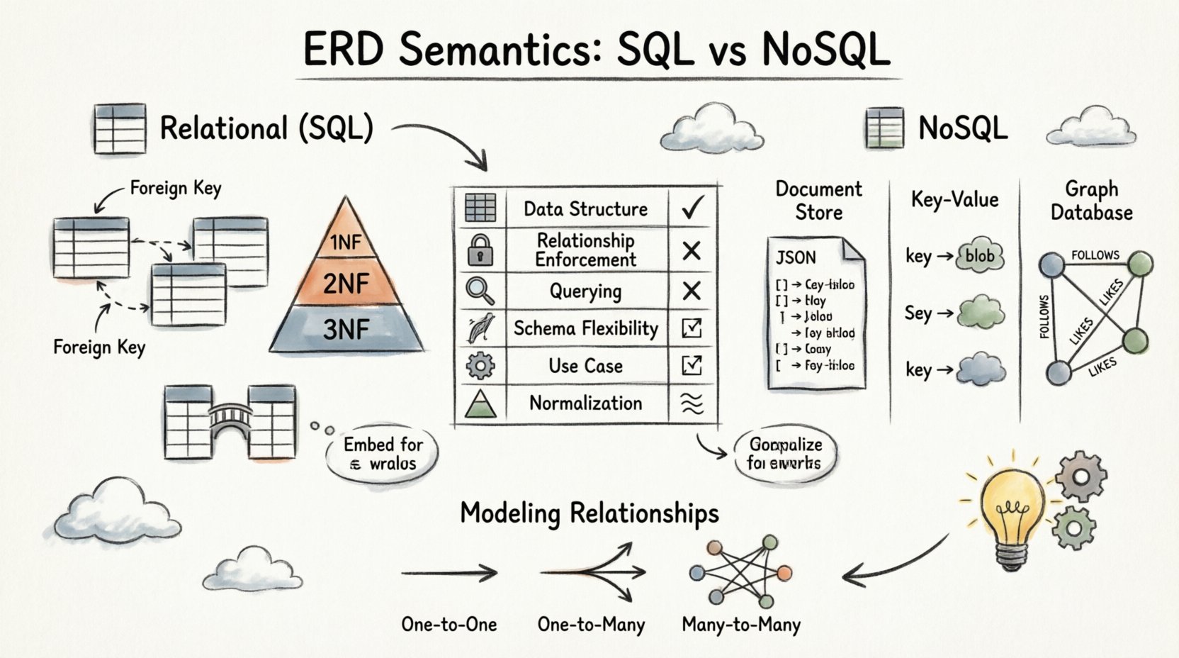
| Feature | Relational (SQL) | Document Store | Graph Database |
|---|---|---|---|
| Data Structure | Tables with Rows and Columns | JSON Documents | Nodes and Edges |
| Relationship Enforcement | Foreign Keys (Strict) | Manual / Application Level | Native Edge References |
| Querying Relationships | JOIN Operations | Lookup or Embedding | Path Traversal |
| Schema Flexibility | Fixed Schema | Dynamic Schema | Semi-Structured |
| Primary Use Case | Transaction Integrity | Content Management / Hierarchies | Networks / Social Graphs |
| Normalization | High (3NF / BCNF) | Low (Denormalized) | Not Applicable |
Modeling Relationships: A Deep Dive 🔗
The way relationships are depicted in an ERD dictates the query patterns and performance characteristics of the application. Let us examine specific cardinalities in detail.
One-to-One Relationships
This is the simplest relationship. One record in Table A corresponds to exactly one record in Table B.
- SQL Implementation: A foreign key in either table with a unique constraint.
- NoSQL Implementation: Often merged into a single document to avoid lookups, or stored separately with a unique reference.
- When to Use: User profiles split from authentication details, or configuration settings linked to specific environments.
One-to-Many Relationships
This is the most common relationship type. One record in Table A relates to many records in Table B.
- SQL Implementation: A foreign key in Table B referencing Table A.
- Document Store: Embed the “Many” side inside the “One” side document as an array. This is efficient for reading the whole hierarchy at once.
- Graph Database: Create an edge from the “One” node to multiple “Many” nodes.
- Consideration: If the “Many” side grows significantly, embedding in a document store may hit storage limits. A hybrid approach (references instead of embedding) might be necessary.
Many-to-Many Relationships
This relationship requires a bridge in SQL, but behaves differently in other systems.
- SQL Implementation: A junction table containing IDs from both parent tables.
- Document Store: Often denormalized. Each document contains a list of IDs or full objects from the related entity. This duplicates data but speeds up retrieval.
- Graph Database: This is the native strength of the model. Nodes are connected directly without an intermediate table.
- Consistency Challenge: In document stores, keeping the lists in sync across multiple documents is difficult. Updates to a shared entity must be propagated to all referencing documents manually.
Schema Evolution and Flexibility 🔄
Software requirements change. Data models must evolve without breaking existing applications. The semantics of the ERD dictate how easily this evolution can happen.
1. Schema Migration in SQL
Changing a relational schema is a significant operation. It often involves locking tables or running migrations during downtime.
- Adding Columns: Generally safe and fast.
- Renaming Columns: Requires rewriting the table structure and updating all dependent queries.
- Changing Data Types: Can be risky if data conversion fails or if application logic relies on the old type.
2. Schema Flexibility in NoSQL
NoSQL systems generally allow schema-less or schema-on-read approaches. The ERD is a guideline rather than a law.
- Adding Fields: You can add new fields to specific documents without affecting others.
- Versioning: It is common to add version numbers to documents to manage different structures over time.
- Trade-off: Lack of enforcement means data quality issues can arise. The application must validate data before writing.
Performance Implications of Modeling Choices ⚡
The structure of your ERD directly impacts query speed. There is no one-size-fits-all solution; the design must align with the access patterns of the application.
1. Read-Heavy Workloads
If the application reads data frequently but updates infrequently, denormalization is beneficial.
- Strategy: Embed related data to reduce the number of queries required.
- Benefit: Fewer I/O operations and lower latency.
- Cost: Increased storage usage and complex update logic.
2. Write-Heavy Workloads
If the application updates data frequently, normalization or separate storage is preferred.
- Strategy: Store data in its most atomic form and join or reference at query time.
- Benefit: Single source of truth; updates happen in one place.
- Cost: Higher read latency due to joins or multiple lookups.
3. Indexing Strategies
Regardless of the database type, the ERD informs where indexes are needed.
- Relational: Indexes are placed on foreign keys and columns used in
WHEREclauses. - Document: Indexes are placed on fields that are queried frequently. Nested fields may require specific indexing syntax.
- Graph: Indexes are placed on node labels and edge properties to speed up traversal starting points.
Hybrid Environments and Polyglot Persistence 🧩
Modern architectures often use multiple database technologies simultaneously. This is known as polyglot persistence. The ERD semantics must bridge these gaps.
1. Data Consistency Patterns
When data spans multiple systems, consistency becomes complex.
- ACID: Relational databases offer strong consistency. Transactions span multiple tables within the same database.
- BASE: NoSQL databases often favor availability and eventual consistency. Transactions may be limited to a single document.
- Saga Pattern: For distributed transactions across systems, a saga pattern manages long-running operations by coordinating local transactions.
2. The Role of the ERD in Hybrid Systems
The ERD acts as a conceptual map. It defines the logical relationships, even if the physical storage differs.
- Mapping: Developers use the ERD to decide which data goes to which store.
- Integration: The diagram helps visualize where data synchronization is required between systems.
- Documentation: It provides a unified view for stakeholders who may not understand the technical differences between the storage engines.
Best Practices for Robust Data Modeling 🛡️
To ensure long-term maintainability and performance, adhere to these principles when designing your ERDs.
- Understand the Domain: Start with the business requirements. Do not model data that does not support a specific use case.
- Choose the Right Tool: Select the database type based on data relationships, not just trends. Use graphs for complex networks, documents for content, and SQL for transactions.
- Document Relationships Explicitly: Clearly label cardinality on the diagram. Ambiguity leads to implementation errors.
- Plan for Growth: Consider how the data volume will scale. Will an embedded array become too large? Will a junction table become a bottleneck?
- Iterate the Design: ERDs are not static. Refine them as the application evolves and new constraints are discovered.
- Validate at the Application Layer: Especially in NoSQL, implement validation logic to ensure data integrity since the database may not enforce it.
Conclusion on Modeling Semantics 📝
The semantics of an Entity Relationship Diagram are not universal; they adapt to the underlying storage technology. In relational systems, the ERD is a contract enforced by the database engine. In NoSQL systems, it is a pattern guide for the application layer. Understanding these distinctions allows architects to design systems that are both scalable and consistent.
By carefully analyzing cardinality, choosing the appropriate storage model, and anticipating future changes, teams can build data layers that support complex business logic without compromising performance. The key lies in aligning the logical model with the physical capabilities of the chosen environment.
Whether working with tables, documents, or graphs, the core principles of identifying entities and defining their connections remain constant. A clear ERD serves as the foundation for reliable software architecture, bridging the gap between business requirements and technical implementation.