


In modern software development, the disconnect between what stakeholders want and what engineers build is a persistent challenge. Business teams articulate value, speed, and user experience. Technical teams focus on scalability, security, and maintainability. When these two perspectives do not align, projects suffer from scope creep, delays, and features that fail to meet user needs. 🛑
To resolve this friction, architects and product owners need a shared language. Visual models serve as this bridge. Among the various methodologies available, the C4 model offers a structured approach to software architecture documentation. By layering detail from context down to code, the C4 model allows non-technical stakeholders to understand the system while giving engineers the precision they need. 🧩
This guide explores how to use the C4 model to translate business requirements into technical design effectively. We will examine each level of the model, discuss mapping strategies, and outline best practices for maintaining alignment throughout the development lifecycle.
Why the Gap Exists: The Communication Barrier 🗣️
The divergence between business and technical teams often stems from vocabulary and abstraction levels. Business requirements are often written in user stories or functional specifications. Terms like “secure payment processing” or “real-time analytics” are clear to a product manager but ambiguous to an architect. Without visual representation, assumptions fill the void.
Common issues include:
- Ambiguity: A requirement states “fast loading,” but the technical team interprets this as server response time, while the business expects user-perceived latency.
- Missing Constraints: Business needs often omit regulatory or security constraints that dictate technical choices.
- Scope Drift: Without a clear architectural baseline, feature requests accumulate without understanding the impact on existing systems.
- Feedback Loops: By the time a technical design is reviewed, it is often too late to pivot without significant cost.
Addressing these issues requires documentation that is accessible yet accurate. The C4 model provides this by offering four distinct levels of abstraction, each tailored to a specific audience and purpose.
Understanding the C4 Model Context 📊
The C4 model is not a tool, but a set of patterns for documenting software architecture. It organizes diagrams into a hierarchy of context and detail. This hierarchy ensures that stakeholders see exactly what they need to see, without being overwhelmed by unnecessary complexity.
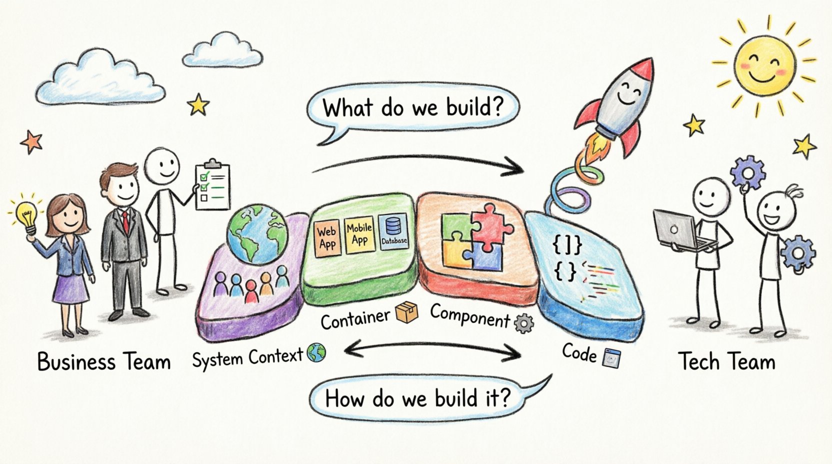
The model consists of four levels:
1. System Context Diagram 🌍
This is the highest level view. It shows the software system as a single box. It highlights the users (actors) and external systems that interact with the software. This diagram is crucial for business stakeholders because it answers the question: “What does this system do, and who uses it?”
2. Container Diagrams 📦
A container represents a deployable unit of software, such as a web application, a mobile app, a database, or a microservice. This level details the technologies used (e.g., Java, Node.js, PostgreSQL) and the communication protocols between containers. It bridges the gap between business functions and technical boundaries.
3. Component Diagrams ⚙️
Within a container, components represent logical modules. These are not physical files but distinct areas of responsibility, such as an authentication service, a reporting engine, or a caching layer. This level helps technical leads understand the internal logic without diving into every line of code.
4. Code Diagrams 💻
At the lowest level, code diagrams show classes and interfaces. These are typically generated from the source code. They are rarely shared with business stakeholders but are vital for onboarding new engineers and understanding complex logic.
Mapping Business Requirements to C4 Levels 🔄
The true power of the C4 model lies in the ability to map specific business requirements to specific architectural layers. This ensures that every technical decision traces back to a business need.
Below is a breakdown of how requirements translate across the C4 hierarchy:
| Business Requirement | C4 Level | Architectural Translation |
|---|---|---|
| Users must be able to log in from mobile and web. | Container | Define a Mobile App Container and a Web App Container communicating via a shared API. |
| System must process payments securely. | Container / Component | Identify a Payment Service Container with an internal Payment Processing Component. |
| Customer data must be retained for 7 years. | Container | Specify a Database Container with retention policies defined in the data store. |
| System must handle 10,000 concurrent users. | Container | Design stateless containers to allow horizontal scaling behind a load balancer. |
| Admins need to audit user actions. | Component | Create an Audit Log Component within the Application Container. |
This mapping process forces clarity. If a requirement cannot be placed in a diagram, it is likely too vague or misaligned with the technical scope.
Level 1: Context Diagrams for Stakeholder Alignment 🤝
The System Context Diagram is the primary tool for initial alignment. When business stakeholders review this diagram, they validate that the system boundaries match their expectations. It is the first checkpoint to prevent scope creep.
Key elements to include:
- The System: A single box labeled with the product name.
- People: Users, administrators, and external actors.
- External Systems: Third-party APIs, legacy databases, or hardware.
- Relationships: Lines connecting actors to the system, labeled with data flow (e.g., “Sends Order”, “Receives Report”).
By keeping this diagram simple, you invite feedback early. If a stakeholder sees a missing external system, it is caught at this stage. It is much cheaper to adjust the context than to refactor the code later. 🛠️
Level 2: Container Diagrams Defining Boundaries 🛡️
Once the context is agreed upon, the Container Diagram details how the system is built. This is often where the most significant technical decisions occur. The choice of containers directly impacts cost, security, and deployment strategy.
When designing containers, consider the following:
- Deployment Unit: Can this be deployed independently? A microservice is a container; a class within a monolith is not.
- Technology Choice: Does this container require a specific language or runtime? Document this clearly.
- Network Boundaries: How does this container talk to others? Is it over HTTP, gRPC, or a message queue?
- Security Zones: Does this container handle sensitive data? It may require specific network isolation.
For business stakeholders, this level answers questions about integration points. If the business plans to integrate with a new partner, the architecture team can see if a new container is needed or if an existing one can be extended.
Level 3: Component Diagrams Managing Complexity 🧠
As systems grow, containers become complex. The Component Diagram breaks down a container into its logical parts. This is essential for development teams to understand responsibilities without reading source code.
Effective component diagrams should:
- Group by Responsibility: Do not group by file structure. Group by business capability (e.g., “Billing”, “Search”, “Notifications”).
- Define Interfaces: Clearly state what each component exposes and consumes.
- Highlight Data Flow: Show how data moves between components within the container.
This level is particularly useful when onboarding new developers. It allows them to grasp the logic of the system quickly. It also aids in identifying redundancy. If two components perform the same function, the architecture can be simplified.
Level 4: Code Diagrams for Engineering Depth 📝
The Code Diagram is the most granular level. It is typically generated automatically from the codebase. While business stakeholders rarely need this, it is critical for technical integrity.
Use cases for this level include:
- Refactoring: Visualizing dependencies before changing core logic.
- Security Audits: Identifying how sensitive data flows through classes.
- Onboarding: Helping new hires understand the specific implementation details.
Automating this generation ensures the documentation remains in sync with the code. Manual updates to code diagrams are prone to error and often become obsolete quickly.
Best Practices for Maintaining Alignment 📐
Creating diagrams is only the first step. Keeping them accurate and useful requires discipline. Here are strategies to ensure the architecture remains aligned with requirements.
1. Treat Documentation as Code 📂
Just as source code is versioned, diagram files should be stored in the same repository. This allows changes to the architecture to be reviewed via pull requests. It ensures that a diagram update is as rigorous as a code change.
2. Iterate Alongside Development 🔄
Do not wait for the project to finish to document the architecture. Update the C4 diagrams during sprint planning. If a new requirement emerges, sketch the change on the diagram before writing code. This validates feasibility early.
3. Define Ownership Roles 👥
Assign responsibility for each diagram. A lead architect might own the Container diagrams, while a team lead manages Component diagrams. This prevents the “everyone owns everything, no one owns anything” scenario.
4. Use Consistent Notation 🎨
Ensure all team members use the same symbols and colors. Consistency reduces cognitive load. If a red box always means “External System,” it should never mean “Database.” Standardization speeds up understanding.
Common Pitfalls to Avoid ⚠️
Even with a structured model, teams can fall into traps that reduce the value of the documentation.
- Over-Engineering Level 4: Spending too much time on code diagrams when business alignment is the goal. Keep the focus on Levels 1 and 2 for stakeholder communication.
- Static Documentation: Creating diagrams that are never updated. An outdated diagram is worse than no diagram because it misleads the team.
- Ignoring Non-Functional Requirements: Focusing only on features (what the system does) and neglecting performance, security, and availability (how the system behaves).
- Tool Dependency: Relying on complex tools that create friction. The goal is communication, not tool mastery. Simple tools that produce clear images are sufficient.
Facilitating Collaboration Between Teams 🤲
The ultimate goal of the C4 model is collaboration. It provides a visual medium where business and technical teams can meet.
Workshops for Context Diagrams
Host workshops where stakeholders draw the System Context diagram together. This collaborative exercise often reveals hidden dependencies. For example, a business user might mention a legacy system that the technical team was unaware of.
Review Sessions for Containers
Conduct architectural reviews focused on the Container Diagram. This is the ideal time to discuss technology choices. Business stakeholders can understand the cost implications of choosing one technology over another.
Feedback Loops
Create a channel for feedback. If a developer implements a feature differently than the diagram, they should update the diagram. This creates a culture of documentation hygiene where the visual model is the source of truth.
Maintaining Architectural Fidelity Over Time 🕰️
Software systems evolve. Requirements change. The architecture must evolve with them. This is known as managing technical debt and architectural drift.
To maintain fidelity:
- Schedule Reviews: Set quarterly reviews of the C4 diagrams to ensure they match the current state.
- Link to Requirements: Where possible, link diagram elements to specific requirements or user stories. This makes it easy to see if a requirement has been implemented or if a component is obsolete.
- Automate Checks: Use static analysis tools to verify that the actual code matches the architectural intent. If a component calls an unauthorized service, the tool flags it.
By treating architecture as a living artifact, teams can prevent the gradual decay that leads to unmanageable systems. The C4 model facilitates this by keeping the view manageable at every level.
Conclusion: A Path to Clarity 🛤️
Bridging the gap between business requirements and technical design is not about translating words into code. It is about translating intent into structure. The C4 model provides the scaffolding for this translation. By starting with context and drilling down to components, teams can ensure that every line of code serves a business purpose.
When business stakeholders can see their requirements reflected in the architecture, trust increases. When engineers understand the “why” behind the design, implementation becomes more purposeful. This alignment is the foundation of sustainable software development. 🚀
Adopting this approach requires discipline, but the return on investment is a system that is easier to maintain, easier to scale, and easier to understand. Start with the context. Map your requirements. Iterate continuously. The result is an architecture that supports, rather than hinders, business goals.