


💡 Key Takeaways
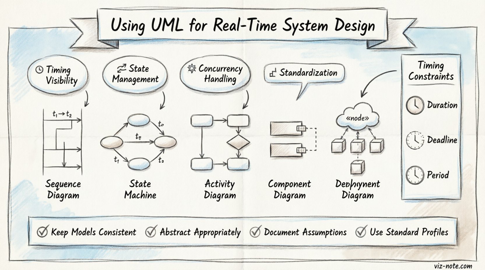
- Timing Visibility: UML provides visual clarity for timing constraints and deadlines in critical systems.
- State Management: State machines effectively model complex control logic and event-driven behaviors.
- Concurrency Handling: Interaction diagrams help identify race conditions and resource conflicts early.
- Standardization: Using standardized profiles ensures consistency across different engineering teams and tools.
Real-time systems operate under strict temporal constraints where correctness depends not only on logical results but also on the time at which they are produced. Designing such systems requires precision, predictability, and rigorous documentation. Unified Modeling Language (UML) serves as a robust standard for visualizing, specifying, constructing, and documenting the artifacts of software systems. When applied specifically to real-time contexts, UML becomes a powerful instrument for managing complexity and ensuring system reliability ⏱️.
This article explores the practical application of UML in the design phase of real-time systems. It covers the selection of appropriate diagrams, the modeling of temporal constraints, and the integration of these models into the development lifecycle without relying on specific commercial tools.
Understanding Real-Time Requirements ⏳
Before selecting modeling techniques, it is essential to distinguish between hard and soft real-time requirements. Hard real-time systems must meet deadlines strictly; failure to do so results in catastrophic system failure. Soft real-time systems allow for occasional deadline misses with degraded performance but no critical failure.
UML helps articulate these requirements visually. Use case diagrams can define the system boundaries and actor interactions, while sequence diagrams can illustrate the timing of message exchanges. The goal is to translate abstract timing requirements into concrete structural and behavioral models.
Core UML Diagrams for Real-Time Systems 📐
Not every diagram type is equally useful for real-time design. Certain diagrams offer more insight into temporal behavior and concurrency. The following list outlines the most critical diagram types for this domain:
- Sequence Diagrams: Essential for showing message flow and timing between objects. They help visualize the sequence of events and response times.
- State Machine Diagrams: Crucial for modeling the lifecycle of an object. They define states, transitions, events, and actions, which are vital for event-driven real-time control.
- Activity Diagrams: Useful for modeling the flow of control or data, similar to flowcharts but with support for concurrency.
- Component Diagrams: Show the physical architecture, including processing units and memory resources.
- Deployment Diagrams: Map software components to hardware nodes, highlighting resource allocation.
Comparing Diagram Utility
| Diagram Type | Primary Focus | Real-Time Relevance |
|---|---|---|
| Sequence | Interaction Order | High (Timing & Latency) |
| State Machine | State Transitions | High (Control Logic) |
| Class | Data Structure | Medium (Memory Layout) |
| Deployment | Hardware Mapping | High (Resource Constraints) |
Modeling Timing Constraints ⏲️
Standard UML does not natively support precise timing annotations. However, extensions and profiles exist to address this. In the context of real-time design, timing information is often added to sequence diagrams or activity diagrams.
When modeling a sequence, designers can annotate message exchanges with time intervals. For example, a request message might be followed by a response within 50 milliseconds. These annotations help stakeholders understand if the proposed architecture can meet the performance criteria.
Timing constraints are often expressed using:
- Duration: The time taken for an activity or interaction.
- Deadline: The maximum time allowed for completion.
- Period: The frequency of recurring events.
By embedding these constraints into the model, teams can perform early feasibility analysis. If the visual model suggests a cycle time exceeds the deadline, the architecture can be adjusted before implementation begins.
State Machines for Control Logic 🔄
Real-time systems often operate in distinct modes or states. For instance, a medical device might have Idle, Monitoring, Alarming, and Treatment states. State machine diagrams are the most effective way to model this behavior.
Each state represents a condition where the system performs specific actions. Transitions occur in response to events. In real-time systems, events are often time-triggered (e.g., a timer expiration) or event-triggered (e.g., a sensor input).
Consider a safety interlock system. The state machine ensures that the system cannot transition to a dangerous state without passing through a safe state. This logical enforcement is critical for reliability. By visualizing these paths, engineers can identify unreachable states or deadlocks during the design phase.
Example Scenario
Imagine a braking system in an autonomous vehicle. The state machine might include:
- Cruising: Maintains speed based on inputs.
- Braking: Activates brakes when an obstacle is detected.
- Emergency: Activates maximum braking force.
Transitions between these states must be instantaneous or within a defined latency window. UML allows the specification of guard conditions and actions associated with these transitions, ensuring the logic is unambiguous.
Concurrency and Resource Management 🧩
Real-time systems frequently involve concurrent processes. Multiple threads or tasks may run simultaneously, sharing resources. This introduces the risk of race conditions and priority inversion.
Activity diagrams support concurrency through fork and join nodes. These nodes indicate where a single flow splits into multiple parallel flows and where they must synchronize again. This visual representation helps identify potential bottlenecks.
For resource management, deployment diagrams play a significant role. They map tasks to specific processors or cores. By analyzing the deployment model, designers can ensure that high-priority tasks are assigned to dedicated hardware resources, preventing lower-priority tasks from starving them.
Verification and Validation 🛡️
Modeling is not just about design; it is also about verification. A well-constructed UML model can serve as a basis for simulation or code generation. While code generation is a specific capability of some environments, the model itself acts as a specification that can be reviewed.
Verification involves checking if the model meets the requirements. Validation ensures the model represents the correct system behavior. In real-time contexts, this includes verifying that the timing constraints in the model are mathematically possible given the system architecture.
Static analysis of the model can detect inconsistencies. For example, a state machine might have a state with no outgoing transitions, leading to a deadlock. Detecting this in the diagram saves significant debugging time later in the development cycle.
Common Pitfalls and Best Practices ⚠️
Even with powerful modeling tools, mistakes can occur. To ensure the effectiveness of UML in real-time design, consider the following best practices:
- Keep Models Consistent: Ensure that the sequence diagram matches the state machine logic. Inconsistencies confuse developers and testers.
- Abstract Appropriately: Do not over-model. Focus on the timing and behavior critical to the real-time aspect, rather than general data structure details.
- Document Assumptions: Real-time models often assume ideal network or hardware performance. Document these assumptions clearly to avoid optimistic estimates.
- Use Standard Profiles: Adopt standard extensions for timing and resource management to ensure compatibility and clarity across teams.
Integration with Development Lifecycle 🔗
UML models are not isolated artifacts. They should be integrated into the broader development lifecycle. This includes version control, change management, and traceability.
Traceability links requirements to design elements. If a timing requirement changes, the model can be updated, and the impact can be assessed by tracing the links to the affected diagrams. This reduces the risk of regression errors.
Furthermore, the model can guide testing strategies. Test cases can be derived directly from state machine transitions and sequence diagram interactions. This ensures that testing coverage is comprehensive and aligned with the design intent.
Future Trends and Standards 🚀
The field of modeling real-time systems continues to evolve. New profiles and standards are being developed to support more complex domains, such as autonomous systems and cyber-physical systems. These standards often extend UML to include specific annotations for timing, scheduling, and resource usage.
Staying informed about these developments ensures that the modeling practices remain relevant and effective. Collaboration with standards bodies and participation in community discussions can provide insights into emerging best practices.
Final Thoughts 📝
Designing real-time systems is a challenging endeavor that demands precision and foresight. UML provides a structured approach to managing this complexity. By leveraging the right diagrams and focusing on timing and concurrency, engineers can create reliable systems that meet their strict operational requirements.
The investment in modeling pays off through reduced defects, clearer communication, and a more robust architecture. As systems become more complex, the role of rigorous design documentation becomes increasingly critical for success.