💡 Key Takeaways
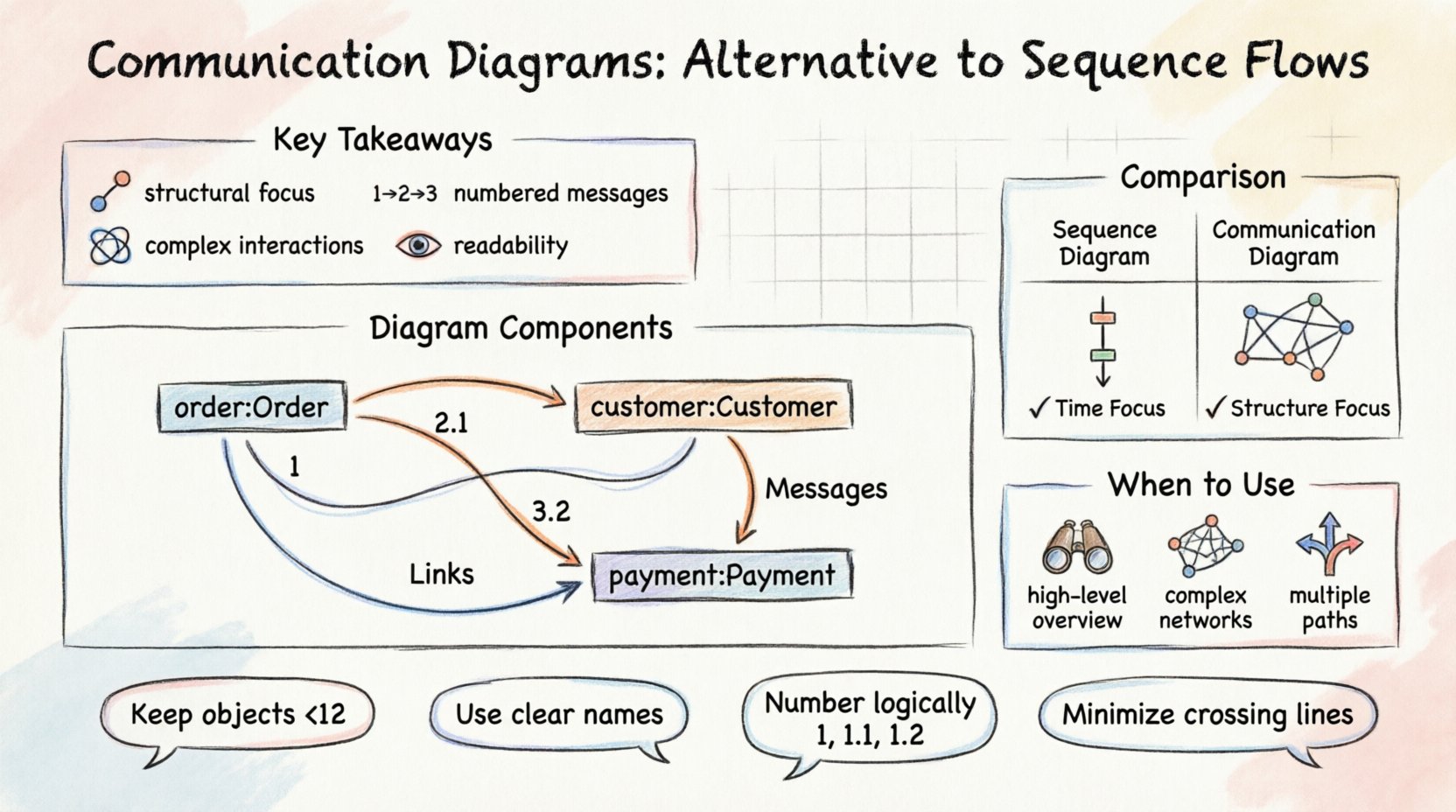
Structural Focus: Communication Diagrams emphasize object relationships and links rather than strict time ordering.
Message Identification: Messages are numbered to indicate sequence, allowing flexibility in visual layout.
Complex Interactions: They are ideal for showing how objects collaborate across a system without vertical timeline constraints.
Readability: Best used for high-level overviews or when the spatial arrangement of objects is more critical than the exact timing.
Understanding the Context of UML Diagrams 📐
In the realm of Unified Modeling Language (UML), interaction diagrams serve as the blueprint for system behavior. Among these, Sequence Diagrams and Communication Diagrams are the most prominent tools used to describe how objects interact to achieve a specific goal. While Sequence Diagrams are widely recognized for their time-oriented approach, Communication Diagrams offer a different perspective that focuses on the structural connections between objects. Understanding when to utilize each is essential for clear system design.
A Communication Diagram, formerly known as a Collaboration Diagram, shifts the focus from the vertical timeline to the horizontal relationships. It visualizes the flow of messages between objects in a way that highlights the static structure of the system. This makes it particularly useful when the arrangement of objects matters more than the precise timing of their interactions.
What is a Communication Diagram? 📊
A Communication Diagram is a type of interaction diagram that shows how objects interact with one another. Unlike the Sequence Diagram, which arranges objects vertically along a timeline, this diagram arranges objects spatially based on their connections. The primary goal is to illustrate the network of links and the flow of messages between instances.
Every Communication Diagram consists of three main components:
Objects: Represented as boxes containing the instance name (e.g., Order:Customer). They appear as nodes in the network.
Links: Represented as lines connecting the objects. These indicate that the objects are aware of each other and can communicate.
Messages: Represented as arrows pointing from one object to another. Each message is numbered to indicate the order of execution.
The numbering system is crucial. In a Sequence Diagram, position on the vertical axis dictates time. In a Communication Diagram, the number next to the arrow dictates time. This allows the designer to place objects anywhere on the canvas as long as the logical flow remains clear.
Structural Elements and Syntax 🛠️
When constructing a Communication Diagram, specific conventions ensure that the model is interpreted correctly by stakeholders and developers.
Object Representation
Objects are depicted as rectangles. The text inside typically includes the instance name followed by the class name, separated by a colon. For example, 1:Product indicates an instance named “1” of the class “Product”. This helps distinguish multiple instances of the same class within the diagram.
Links and Associations
Links represent the structural relationships defined in the class diagram. If two objects can communicate, a line must exist between them. If a message travels from Object A to Object B, a direct link must be present. If the objects are not directly linked, the message flow implies a traversal through other objects, which should be represented by intermediate links.
Message Flow
Messages are arrows. They can be solid lines for synchronous calls or dashed lines for return messages. The order is indicated by a number. For example, a message labeled “1” happens before a message labeled “2”. This numbering allows the diagram to remain flexible in layout while maintaining logical sequence.
Sequence Diagram vs. Communication Diagram ⚖️
Choosing between these two interaction models depends on the information you wish to convey. Both describe the same underlying interactions but present them differently.
Feature | Sequence Diagram | Communication Diagram |
|---|---|---|
Focus | Time and sequence of messages. | Structural organization and links. |
Layout | Vertical timeline. | Spatial arrangement of objects. |
Readability | Best for detailed timing and loops. | Best for overview of object connections. |
Complexity | Can become tall with many objects. | Can become cluttered if too many links exist. |
Message Order | Implicit (top to bottom). | Explicit (numbered arrows). |
When the order of operations is the most critical detail, a Sequence Diagram is often preferred. However, when the relationship between objects is the primary concern, the Communication Diagram provides a clearer picture.
When to Use Communication Diagrams 🎯
There are specific scenarios where the Communication Diagram is the superior choice for documentation and design.
High-Level System Overviews
If you are presenting the system to a non-technical stakeholder, a Communication Diagram can be more approachable. It shows the “who talks to whom” without the complexity of activation bars and strict timing.
Complex Object Networks
In systems where objects are deeply interconnected, the spatial layout of a Communication Diagram can reveal patterns that a vertical Sequence Diagram might obscure. It allows the designer to group related objects together visually.
Multiple Interaction Scenarios
When a single scenario involves many different paths, a Communication Diagram can sometimes consolidate the information more efficiently. Instead of stacking multiple Sequence Diagrams, one Communication Diagram can show the network of interactions.
Best Practices for Designing Communication Diagrams 📝
To ensure these diagrams remain effective tools for communication, follow these guidelines during creation.
Keep Object Counts Manageable
Like any diagram, complexity reduces readability. If a diagram contains more than 10 or 12 objects, it may become difficult to parse. Consider breaking a complex interaction into multiple diagrams, each focusing on a specific subsystem.
Use Clear Naming Conventions
Ensure object names are descriptive. Instead of obj1, use invoice:Invoice. This helps readers understand the context of the interaction without referring back to the class diagram constantly.
Number Messages Logically
The numbers should follow a logical sequence. If a message triggers a nested interaction, use decimal numbering (e.g., 1.1, 1.2). This clarifies the hierarchy of calls without needing separate diagrams.
Minimize Cross-Links
Avoid having arrows cross over other objects or lines unnecessarily. While the layout is flexible, a clean visual path reduces cognitive load. If the diagram becomes too tangled, consider rearranging the objects.
Reading and Interpreting the Flow 🧠
When reviewing a Communication Diagram, start by identifying the initiating object. Look for the message labeled “1”. Trace the path of subsequent messages to understand the lifecycle of the operation. Pay attention to return messages, which are often shown as dashed arrows.
It is also important to note that Communication Diagrams do not explicitly show the concept of an activation bar. In a Sequence Diagram, an activation bar indicates when an object is busy processing a message. In a Communication Diagram, this is implied by the sequence of messages. If a message takes a long time to process, it is not visually represented unless annotated.
Limitations and Considerations ⚠️
While powerful, Communication Diagrams have limitations. They are less effective at showing timing constraints. If a system relies on strict deadlines or timeouts, the Sequence Diagram is more appropriate. Additionally, they do not easily show the internal state of an object during the interaction.
Another consideration is the maintenance of the diagram. If the system architecture changes significantly, the links in a Communication Diagram must be updated to reflect new relationships. This can be more labor-intensive than updating a Sequence Diagram if the object structure is extensive.
Conclusion 🏁
Communication Diagrams provide a valuable alternative to Sequence Flows in UML modeling. By prioritizing object relationships over strict timing, they offer a unique perspective on system interactions. When used correctly, they simplify complex networks and highlight the structural integrity of the design. Whether for high-level overviews or detailed collaboration mapping, this diagram type remains a staple in the architect’s toolkit.
Integrating both Sequence and Communication Diagrams into the documentation process often yields the best results. One can establish the timing logic while the other clarifies the structural connections. This dual approach ensures that both the functional and structural aspects of the system are thoroughly understood by all team members.