


💡 Key Takeaways
Functional Focus: Use Case Diagrams model what a system does, not how it does it, focusing on user goals.
Actor Clarity: Clearly defining internal and external actors prevents scope creep and ambiguity.
Relationship Types: Understanding Include, Extend, and Generalization relationships ensures accurate requirement mapping.
Requirement Validation: These diagrams serve as a communication bridge between stakeholders and technical teams.
In the realm of software engineering and systems design, clarity is paramount. Before a single line of code is written, requirements must be understood by everyone involved. Use Case Diagrams stand as a cornerstone of the Unified Modeling Language (UML), providing a visual representation of the interactions between users and a system. They are not merely drawings; they are functional contracts that define the boundaries of a solution. This guide explores how to effectively utilize these diagrams to capture functional requirements with precision and authority.
Understanding the Purpose 🎯
At its core, a Use Case Diagram describes the system’s behavior from the perspective of external entities. It answers the question: “What does the system do for the user?” Unlike data flow diagrams or sequence diagrams, which focus on internal mechanics or timing, Use Case Diagrams focus on goals and value delivery. They are instrumental in requirements gathering because they translate technical capabilities into user-centric actions.
When capturing functional requirements, the goal is to identify specific services or functions that a system must perform to meet the needs of its users. A Use Case represents one such service. It is a complete unit of functionality that produces a result of value to a specific actor. By mapping these out, teams can ensure that every requirement aligns with a tangible user goal.
Core Components of the Diagram 🧩
To build an effective diagram, one must understand the standard elements defined in the UML specification. These elements form the vocabulary of the diagram.
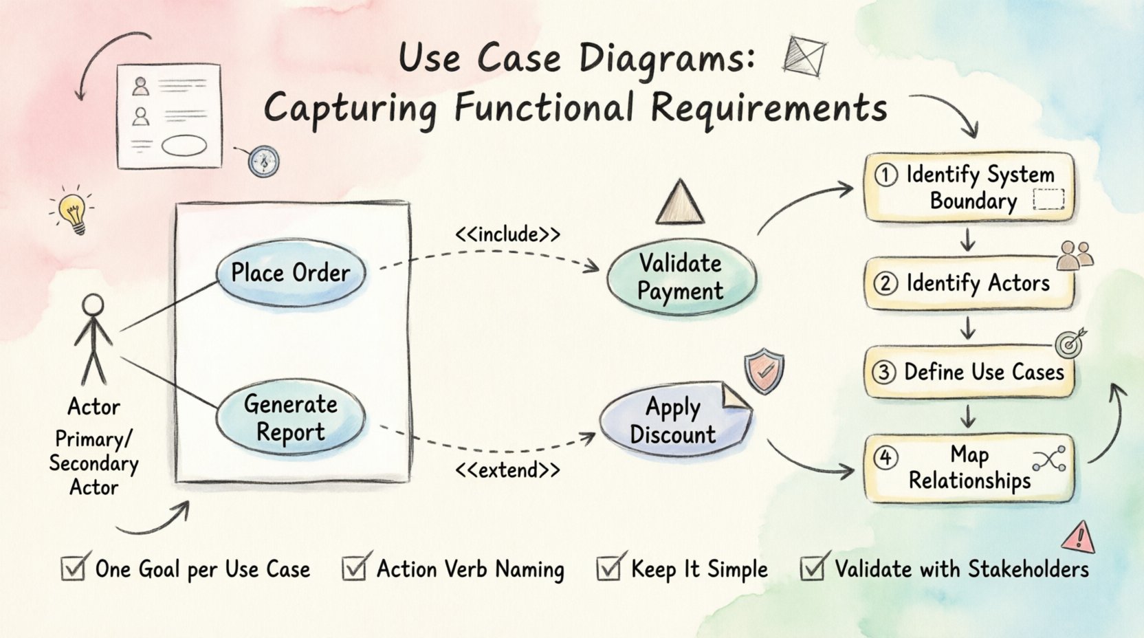
1. Actors 👤
Actors represent the roles played by users or external systems that interact with the subject system. They are the “who” of the equation. An actor does not necessarily have to be a human being; it can be another software system, a hardware device, or a time-triggered process.
Primary Actors: Those who initiate the interaction to achieve a goal.
Secondary Actors: Those that provide services to the system but do not initiate the process.
It is crucial to define actors based on their role, not their identity. For instance, instead of labeling an actor “John,” label the role “Administrator.” This ensures the diagram remains valid even if the person in the role changes.
2. Use Cases 🔄
A Use Case is an oval shape representing a specific function or goal. It describes a sequence of actions that results in a measurable outcome of value to an actor. For example, “Place Order” or “Generate Report” are typical use cases.
Each use case should be atomic, meaning it performs a single distinct function. Combining multiple functions into one use case can lead to complexity and ambiguity in requirements.
3. Associations 🔗
Association lines connect actors to use cases. They indicate that the actor interacts with that specific function. The line does not imply a direction of data flow but rather a relationship of interaction. In some standards, arrows are used to indicate who initiates the use case.
Capturing Functional Requirements 📝
The process of translating functional requirements into a Use Case Diagram involves several structured steps. This ensures that no critical functionality is overlooked.
Step 1: Identify the System Boundary
Define what is inside the system and what is outside. This boundary separates the scope of the project from the environment. Everything inside the box is part of the system; everything outside is an actor or external dependency.
Step 2: Identify the Actors
Conduct interviews or workshops with stakeholders to determine who interacts with the system. List all potential roles. Ask questions like: “Who triggers this process?” and “Who receives the output?”
Step 3: Define the Use Cases
For each actor, identify the goals they want to achieve. Each goal becomes a use case. Ensure that every use case provides value to at least one actor. If a function exists but no actor benefits from it, it may be unnecessary.
Step 4: Map the Relationships
Connect actors to use cases using associations. Review the connections to ensure they accurately reflect the system’s intended behavior. If an actor interacts with multiple functions, ensure all relevant lines are drawn.
Advanced Relationships 🤝
Simple associations are not always enough to describe complex requirements. UML provides specific relationship types to handle reuse, extension, and hierarchy.
Include Relationship ➕
An Include relationship indicates that one use case incorporates the behavior of another. This is used to break down complex processes into smaller, reusable steps. For example, the “Place Order” use case might include “Validate Payment.” The “Place Order” process cannot complete without the “Validate Payment” step.
Extend Relationship ➡️
An Extend relationship indicates optional behavior. It allows a use case to be extended by another under specific conditions. For example, “Apply Discount” might extend “Place Order” only if the user has a membership. This helps manage optional features without cluttering the main flow.
Generalization Relationship 📉
Generalization allows actors or use cases to inherit characteristics from a parent. For actors, it means a specific role inherits the capabilities of a broader role. For use cases, it means a specific function inherits the logic of a general function. This reduces redundancy in the diagram.
Best Practices for Requirement Modeling 🛡️
To maintain the integrity of the requirements, adhere to these established practices.
Practice | Description |
|---|---|
One Goal per Use Case | Ensure each oval represents a single, distinct user goal. |
Consistent Naming | Use action verbs for use cases (e.g., “Process Return”) and nouns for actors. |
Keep it Simple | Avoid unnecessary complexity. If a diagram is hard to read, simplify it. |
Validate with Stakeholders | Review the diagrams with users to confirm they match their understanding of the system. |
Common Pitfalls to Avoid ⚠️
Even experienced architects can fall into traps when modeling requirements. Awareness of these common mistakes can save significant time during development.
Mixing Levels of Abstraction: Do not mix high-level goals with low-level implementation details. Keep the diagram focused on user value.
Ignoring Non-Functional Requirements: While Use Case Diagrams focus on functionality, they do not capture performance or security constraints. These should be documented separately.
Over-Modeling: Creating too many use cases can lead to analysis paralysis. Focus on the critical paths first.
Assuming Flow Control: Do not try to depict the detailed logic of the interaction. That belongs in the Use Case Description or Sequence Diagram.
The Value of Visual Communication 🗣️
The ultimate value of a Use Case Diagram lies in its ability to facilitate communication. It serves as a shared language between business stakeholders and technical teams. When a business analyst describes a requirement verbally, it can be interpreted differently by different developers. A diagram provides a visual anchor that reduces ambiguity.
During the development lifecycle, these diagrams act as a reference point. If a feature request comes in that seems out of scope, the team can refer back to the diagram to see if it fits the established actor-use case relationships. This helps in managing scope creep effectively.
Conclusion 🏁
Use Case Diagrams are a powerful tool for capturing functional requirements within the UML framework. By focusing on goals, actors, and interactions, they provide a clear map of system behavior. When constructed with attention to detail and adherence to best practices, they become a reliable foundation for software development. They do not replace detailed specifications, but they guide the creation of those specifications with clarity and purpose.
As you move forward with your projects, remember that the diagram is a living document. It should evolve as requirements are refined and new insights are gained. Maintain its accuracy to ensure the final product meets the needs of the users it serves.