Now Reading: Comprehensive Case Study on UML State Diagrams for a Temperature Control System
-
01
Comprehensive Case Study on UML State Diagrams for a Temperature Control System
Comprehensive Case Study on UML State Diagrams for a Temperature Control System
Introduction
UML (Unified Modeling Language) state diagrams are powerful tools for modeling the dynamic behavior of systems, capturing how they transition between states in response to events. They are widely used in software engineering to design and analyze systems with complex behaviors, such as embedded systems, user interfaces, and business processes. This case study focuses on a UML state diagram for a temperature control system, likely used in a thermostat or HVAC system, to illustrate key UML concepts. It also provides step-by-step guidance on creating such diagrams using Visual Paradigm, a leading UML modeling tool. To enhance understanding, additional examples, such as a vending machine and a traffic light system, are included to demonstrate the versatility of state diagrams.
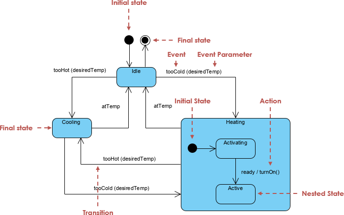
Description of the Temperature Control System
The temperature control system maintains a desired temperature by switching between heating and cooling modes based on environmental conditions. The system’s behavior is modeled as follows:
- States:
- Idle: The system is inactive, waiting for temperature changes.
- Cooling: The system actively cools the environment when the temperature exceeds the desired level.
- Heating: A composite state managing the heating process, containing:
- Activating: The heating system is initialized.
- Active: The heating system actively maintains the temperature.
- Final State: Represents system termination, potentially reachable from Idle.
- Transitions:
- From Initial State to Idle: The system starts in Idle (no event specified).
- From Idle to Cooling: Triggered by tooHot(desiredTemp), where desiredTemp is the target temperature.
- From Cooling to Idle: Triggered by atTemp, indicating the temperature is at the desired level.
- From Idle to Heating.Activating: Triggered by tooCold(desiredTemp).
- From Heating.Activating to Heating.Active: Triggered by ready / turnOn, with turnOn as an action.
- From Heating.Active to Idle: Triggered by atTemp.
- From Idle to Final State: Not explicitly detailed but implied as a termination condition.
- Events:
- tooHot(desiredTemp): Temperature exceeds the desired level.
- tooCold(desiredTemp): Temperature falls below the desired level.
- atTemp: Temperature reaches the desired level.
- ready: Heating system is ready to operate.
- Actions:
- turnOn: Executed during the transition from Activating to Active, activating the heating mechanism.
This diagram effectively captures the system’s lifecycle, showing how it responds to temperature changes and manages heating and cooling processes.

Key Concepts of UML State Diagrams
UML state diagrams are part of the UML standard for modeling system behavior. They are particularly useful for event-driven systems, where state changes are triggered by specific events. Below are the key concepts, illustrated with examples from the temperature control system and supported by additional examples:
- States:
- A state represents a condition or situation during a system’s lifecycle, where it performs specific activities or waits for events.
- Example (Temperature Control): The Idle state indicates the system is inactive, while Cooling and Heating represent active temperature regulation.
- Example (Vending Machine): A vending machine might have states like Idle (waiting for user input), Selecting (user choosing a product), and Dispensing (delivering the product).
- Example (Traffic Light): States include Red (stop), Green (go), and Yellow (caution).
- Transitions:
- Transitions are directed arrows showing state changes triggered by events, often with associated actions or guard conditions.
- Example (Temperature Control): The transition from Idle to Cooling is triggered by tooHot(desiredTemp), indicating a high temperature.
- Example (Vending Machine): A transition from Selecting to Dispensing occurs when the user confirms their selection (selectItem).
- Example (Traffic Light): A transition from Green to Yellow is triggered by a timer event (timerExpired).
- Events:
- Events are stimuli that trigger transitions, such as user actions, system signals, or time-based triggers.
- Example (Temperature Control): The event atTemp triggers a return to Idle from Cooling or Heating.
- Example (Vending Machine): The event insertCoin triggers a transition from Idle to Selecting.
- Example (Traffic Light): The event timerExpired drives cyclic transitions between Red, Green, and Yellow.
- Actions:
- Actions are activities performed during transitions, state entry, or state exit.
- Example (Temperature Control): The action turnOn is executed when transitioning from Heating.Activating to Heating.Active.
- Example (Vending Machine): An action dispenseItem occurs when transitioning to the Dispensing state.
- Example (Traffic Light): An action updateSignal might update the light display during a transition.
- Initial and Final States:
- The initial state (solid circle) marks the system’s starting point, while the final state (circle with a concentric circle) indicates termination.
- Example (Temperature Control): The initial state leads to Idle, and the final state is reachable from Idle, possibly when the system is turned off.
- Example (Vending Machine): The initial state leads to Idle, and a final state might represent a system shutdown.
- Example (Traffic Light): A final state could represent a system failure or maintenance mode.
- Composite States:
- Composite states contain nested substates, allowing hierarchical modeling of complex behaviors.
- Example (Temperature Control): The Heating state is composite, containing Activating and Active substates.
- Example (Vending Machine): A Payment state might be composite, with substates like CardProcessing and CashProcessing.
- Example (Traffic Light): A composite state like EmergencyMode could include substates for flashing lights or manual control.
- Guard Conditions:
- Guard conditions are boolean expressions that must be true for a transition to occur.
- Example (Temperature Control): A guard like [temperature > desiredTemp + threshold] could ensure the tooHot transition only occurs when the temperature significantly exceeds the target.
- Example (Vending Machine): A guard [paymentSufficient] ensures the transition to Dispensing only occurs if enough money is inserted.
- Example (Traffic Light): A guard [emergencySignalReceived] might trigger a transition to an emergency state.
These concepts, rooted in the UML standard, enable precise modeling of system behavior, as seen in the temperature control system and other examples.
Using Visual Paradigm to Create UML Diagrams
Visual Paradigm is a robust UML modeling tool that simplifies the creation of state diagrams and other UML artifacts. It offers an intuitive interface, drag-and-drop functionality, and features like syntax checking and team collaboration. Below is a step-by-step guide to creating a state diagram like the one for the temperature control system:
- Installation and Setup:
- Download Visual Paradigm from its official website or use Visual Paradigm Online for cloud-based diagramming.
- Create a new project by selecting “New Project” in the application.
- Create a State Diagram:
- In the project explorer, right-click and select “Add Diagram” > “State Machine Diagram” to open a blank canvas.
- Add States:
- Use the “State” tool to drag and drop states onto the canvas, naming them “Idle,” “Cooling,” and “Heating.”
- For composite states like Heating, create a state and add substates (Activating, Active) inside it using the sub-diagram feature or by drawing nested states.
- Add Transitions:
- Use the “Transition” tool to connect states by clicking and dragging from the source to the target state.
- Label transitions with events and actions, e.g., [tooHot(desiredTemp)] or ready / turnOn.
- Add Initial and Final States:
- Use the “Initial State” tool to add a solid circle and connect it to Idle.
- Use the “Final State” tool to add a circle with a concentric circle, connecting it from Idle if needed.
- Label Events and Actions:
- Double-click transitions to specify events (e.g., tooCold(desiredTemp)) and actions (e.g., turnOn).
- Include guard conditions if applicable, e.g., [temperature > desiredTemp + threshold].
- Verify and Refine:
- Use Visual Paradigm’s syntax checking to ensure UML compliance.
- Adjust the layout using alignment tools for clarity and readability.
- Generate Documentation and Share:
- Export the diagram as a PNG, JPG, SVG, or PDF for sharing.
- Use the “Doc. Composer” feature to generate detailed documentation.
- With Visual Paradigm Online, collaborate in real-time with team members.
Visual Paradigm Features:
- Resource Catalog: Reuse elements across diagrams for consistency.
- Sub-Diagrams: Manage complex composite states like Heating.
- Code Engineering: Generate or reverse-engineer code from diagrams.
- Team Collaboration: Supports simultaneous editing and cloud storage.
Example Workflow for Temperature Control System:
- Start with the initial state connected to Idle.
- Add Cooling and Heating states, with Heating containing Activating and Active substates.
- Create transitions: Idle to Cooling (tooHot(desiredTemp)), Cooling to Idle (atTemp), Idle to Heating.Activating (tooCold(desiredTemp)), Activating to Active (ready / turnOn), and Active to Idle (atTemp).
- Add the final state from Idle.
- Verify syntax and export the diagram.
Additional Examples
To deepen understanding, here are two additional UML state diagram examples:
- Vending Machine:
- States:
- Idle: Waiting for user input.
- Selecting: User chooses a product.
- Payment: User makes payment.
- Dispensing: Product is dispensed.
- Returning Change: Change is returned.
- Transitions:
- Idle → Selecting: Triggered by insertCoin.
- Selecting → Payment: Triggered by selectItem.
- Payment → Dispensing: Triggered by paymentConfirmed with guard [paymentSufficient].
- Dispensing → Returning Change: Triggered by itemDispensed with action dispenseChange.
- Returning Change → Idle: Triggered by changeReturned.
- Use Case: This diagram models a vending machine’s transaction process, ensuring all steps (coin insertion, selection, payment, dispensing) are clearly defined.
- States:
- Traffic Light System:
- States:
- Red: Vehicles stop.
- Green: Vehicles go.
- Yellow: Vehicles prepare to stop.
- Transitions:
- Red → Green: Triggered by timerExpired [duration = 30s].
- Green → Yellow: Triggered by timerExpired [duration = 30s].
- Yellow → Red: Triggered by timerExpired [duration = 5s].
- Use Case: This cyclic diagram models a traffic light’s predictable behavior, useful for traffic management systems.
- States:
- Order Processing System:
- States:
- Placed: Order is submitted by the customer.
- Processing: Order undergoes payment and inventory checks.
- Shipped: Order is dispatched.
- Delivered: Order reaches the customer.
- Canceled: Order is canceled.
- Transitions:
- Placed → Processing: Triggered by orderVerified with guard [paymentValid && inventoryAvailable].
- Processing → Shipped: Triggered by orderPacked with action notifyCustomer.
- Shipped → Delivered: Triggered by deliveryConfirmed.
- Placed → Canceled: Triggered by customerCancel.
- Processing → Canceled: Triggered by paymentFailed or inventoryUnavailable.
- Use Case: This diagram models an e-commerce order lifecycle, highlighting critical decision points like payment validation.
- States:
These examples demonstrate the versatility of UML state diagrams across different domains, from consumer electronics to business processes and infrastructure systems.
Conclusion
UML state diagrams are invaluable for modeling the dynamic behavior of systems, providing a clear, visual representation of states, transitions, and events. The temperature control system example illustrates how these diagrams capture complex behaviors, such as hierarchical states and event-driven transitions. Additional examples, like vending machines, traffic lights, and order processing systems, show their applicability across diverse scenarios. Visual Paradigm enhances the creation process with its user-friendly interface, syntax checking, and collaboration features, making it an excellent tool for both novice and experienced designers. By leveraging UML state diagrams and tools like Visual Paradigm, developers can design robust, maintainable systems and communicate designs effectively to stakeholders.
Key Citations:
-
- State Machine Diagrams | Unified Modeling Language (UML) | GeeksforGeeks
- All You Need to Know about State Diagrams | Visual Paradigm
- UML State Machine | Wikipedia
- What is State Machine Diagram? | Visual Paradigm
- UML State Diagrams Explained | Baeldung on Computer Science
- Unified Modeling Language (UML) Diagrams | GeeksforGeeks


